
IPv4 is still the king of the network layer, but the urge for a modern protocol reflecting the needs of modern applications is getting bigger and bigger. As a Network Engineer, you must know how IPv6 works and why it has been designed this way because the future is every day closer and it’s better to prepare for it. This is the purpose of this article, giving you an overview of this protocol, its logic, and explaining what improvements make it better of IPv4. With this solid ground knowledge, you will be ready to configure network devices to support the new version of the Internet Protocol. To do that, it’s time to learn how IPv6 addressing works.
IPv6 overcomes the limits of IPv4
Think how much the world changed in the past forty years. More than that, think how much technology has evolved in that time span. We made a lot of improvements in any technology fields, from cars to houses, from production chain to healthcare. All in all, everything changed, and this if for a reason: our needs changed. More than that, our needs keep changing, and that’s the reason behind the need for a new Internet Protocol. IPv4 has been designed in the late seventies, and since we are still using it in 2016 it means that it is pretty functional. However, the way we use it changed over the years, so that in 1994 we started to develop IPv6, knowing that IPv4 wouldn’t last forever. Let’s see why.
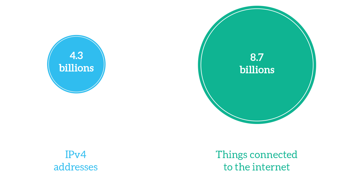
The Internet Protocol is designed to give an address to devices and to allow remote communication between them. However, in the seventies, devices that had to communicate were only a few. Only some supercomputers and servers were connected to the Internet. However, IPv4 was designed to support the growth of devices connected to the Internet. Devices continued to grow exponentially, and at some point, we realized that we couldn’t waste IP addresses anymore: so we moved from classful addressing to classless addressing (find out more in our IPv4 article). This way, we delayed the transition of several years, but as of now, the things connected to the Internet have already passed the available IPv4 addresses, for several factors. First, we actually have more devices than we used to, such as smartphones, laptops, and tablets. Internet of Things (IoT) is a growing technology where virtually anything has an IP address, from fridges to cars; and we use broadband Internet connections that are always on, so we need IP addresses 24/7.
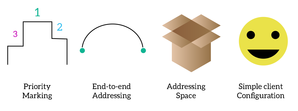
Although the shortage of IPv4 addresses is probably the most important reason for having a new addressing system, IPv4 has several limitations that we can overcome now with IPv6:
- Priority marking – Many modern applications require real-time traffic, such as Voice over IP or Video Streaming, and this traffic has to travel over the network before anything else, to make allow the application to be “real-time”. With IPv4, we have the possibility to mark special traffic like that with a priority, but this complex not very practical, since we have to check and mark every single packet.
- End-to-end addressing – To postpone the shortage of IPv4 addresses, after adopting a classless addressing system we started to use Network Address Translation to convert multiple private IPv4 addresses into a single or a few public IPv4 addresses: this results in addresses changing over the path, and sender and receiver do not know the “true” IP address of one another. This can be a problem for some security applications.
- Addressing space – As we already said, IPv4 cannot offers as many addresses as we need them now.
- Simple client configuration – To configure an IPv4 address on a client (end-user device), you have either to put it manually in the device’s configuration or you have to rely on a server on that subnet (a DHCP server), there is no automatic way to craft an IP address.
Now that we know the reasons behind the creation of this new protocol, it’s time to introduce Internet Protocol version 6 with all its features and characteristics: let’s have a look at the next section.
IPv6 addressing: prefixes and addresses
Just like in the previous version, IPv6 works with addresses. However, in version 4 an address is 32-bits long, while with IPv6 it is 128-bits long. This means that we have 2128 possible addresses (the number is 340,282,366,920,938,463,463,374,607,431,768,211,456 and reads as 340 undecillion). This is a huge number, and representing it in a dotted notation would be long and hard to read: instead of four numbers in dotted notation we would have 16 numbers. So, we changed the way we represent the address.
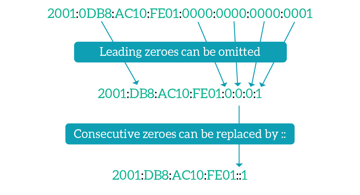
An IPv6 address is represented in blocks of four hexadecimal digits, with columns to divide each block from the next one. One single hexadecimal digit can represent four bits, so each block will represent two bytes (16 bits). This way, we reduced the number of blocks from 16 to 8, but we can do something more. In IPv6 addresses, it is very likely that you will find several zeroes, as the addressing space is way bigger than the one we need today, so you are going to write entire blocks of zeroes. Fortunately, leading zeroes in each block can be omitted. This way we have a pretty compact address, but we can do a lot better. If you have several consecutive blocks that are worth zero, you can represent them as a single empty block (two consecutive columns). This can obviously be done only once because if you do that twice in the same address you won’t know how to expand the address to its “normal” state. So, now we have an extremely compact address: take a look at the picture below.
It is important to remember that we can reduce and compress the way we represent an IPv6 address for the sake of readability, but we cannot actually reduce the way it is stored in the memory of the computer: it will always occupy 128 bits and be treated as a 128-bits long number. With that in mind, we know that IPv4 addresses could be divided into three parts: the first bits were for the major, the ones in the middle were the Subnet ID and the last ones where the Host ID. IPv6 is a little bit different because we do not have majors anymore. Instead, the address is divided into two equals parts: the first 64 bits are the Network Prefix, and the last 64 bits are the Interface ID.
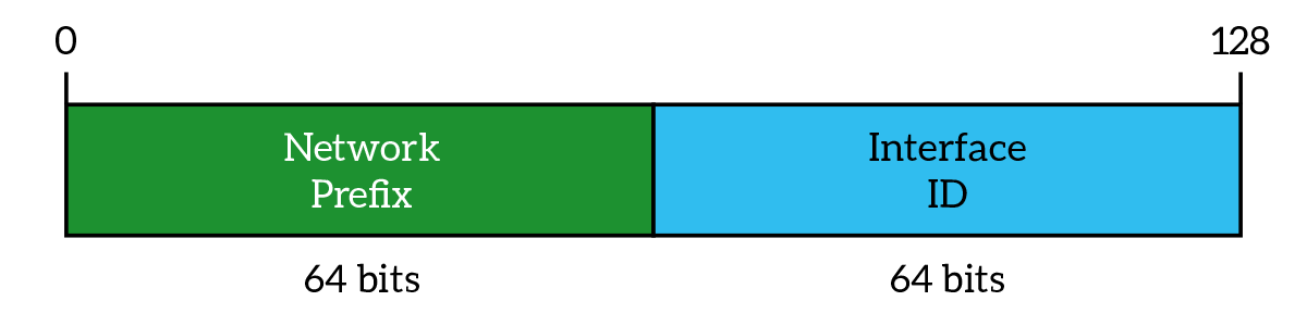
The network prefix can be compared to the IPv4 Subnet ID, it represents a group of IPv6 addresses. The Interface ID is pretty similar to the IPv4 Host ID, but with a simple difference in the concept. With version 4, we were used to the fact that IP addresses were host-related, but the truth is that an IP address is related to the network interface (NIC), and if a host has multiple NICs it can have multiple addresses. This aesthetic error was also corrected with IPv6. More than that, in IPv6 we do not have subnet masks, but only a CIDR-like notation (slash notation) to indicates how is effectively long the network prefix, which is generally /64.
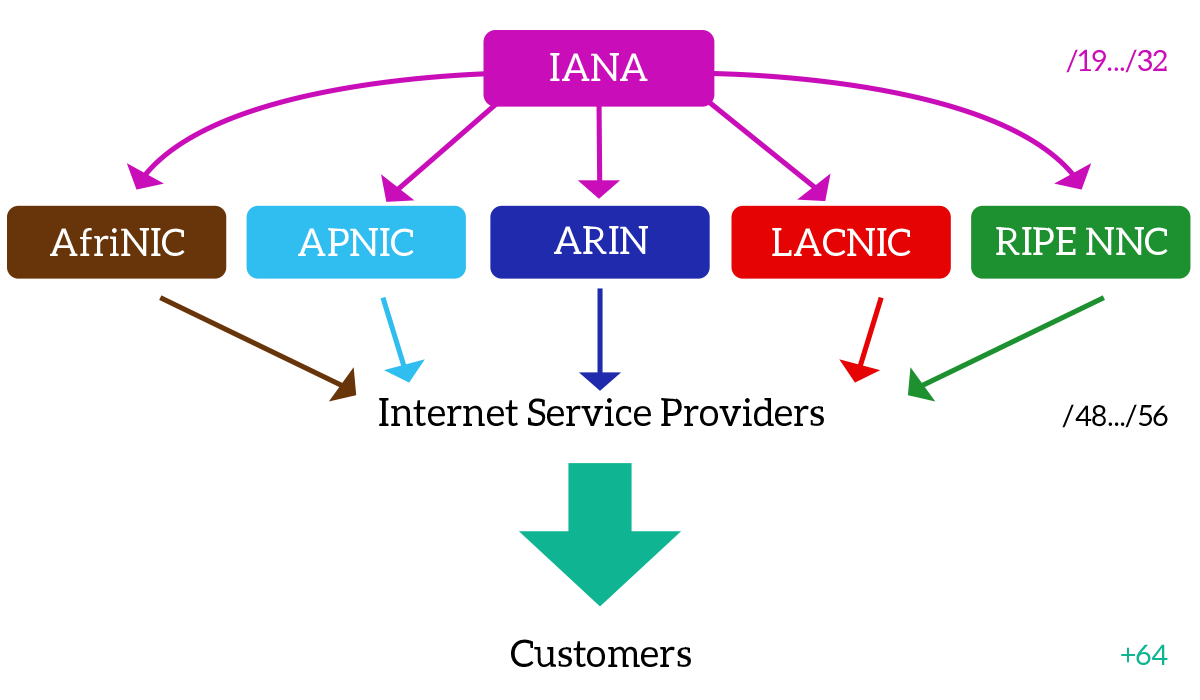
You can imagine that the one giving you an IP address, in this case, an IPv6 address, is your Internet Provider. This is totally correct, but where do providers obtain addresses from? Let’s change the point of view, starting from the top instead of the bottom. The Internet Architecture Board (IAB) and the Internet Corporation for Assigned Names and Numbers (ICANN) design the Internet and then delegates the Internet Assigned Numbers Authority (IANA) to distribute addresses worldwide. However, IANA does not gives addresses directly to providers, but instead to the five Regional Internet Registry (RIRs). Each RIR, administer the assignment of IP addresses for a region: AfriNIC covers Africa, APNIC is the one in Asia-Pacific, ARNIC is for North America, LACNIC covers Latin America and the Caribbean and RIPE NNC is the one in charge for Europe. They are the ones to assign addresses to Internet Providers (or big enterprises), while ISP will give addresses to final customers. Remember that you can obtain your very own address only from an RIR, because from a provider you will only borrow an address from the ISP’s addressing space. Given that, for IPv6, IANA gives network prefixes with size going from /19 to /32 to RIRs, and they then assign addressing space in blocks of /48 to /56 to ISPs. The final customer should obtain exactly a /64 prefix, but this is not always true, so even smaller prefixes could be assigned to the end-user.
IPv6 network prefixes are strictly assigned according to geographic location. This idea was applied also in IPv4, and at the beginning of IPv6, but without being a strict rule. Now, this is done completely by-the-book, because with IPv6 we have a huge load of addresses and a router cannot be able to remember a different route for each prefix, instead, it should only know how to reach Asian prefixes, American prefixes and so on, saving a lot of memory and computational power on the router. We will explain this concept, known as summarization, later in the CCNA course.
In order to solve the shortage of addressing space, using 128-bits long IP addresses in an IPv4 packet would have been enough, but the shortage of addresses is not the only problem we are trying to solve. Because of all the reasons we already explained earlier, we need not only a new addressing system, but instead a brand-new Network-Layer Framework, at the center of which we have the IPv6 packet. As you can see from the picture below, the header of the packet is much simpler and with fewer fields than the one we used in IPv4. Let’s see the purpose of each field.
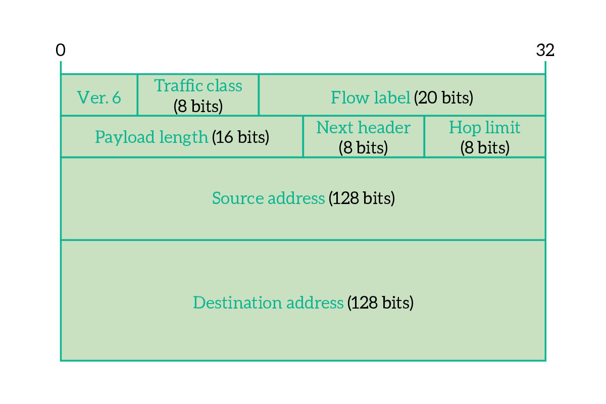
The first thing you see looking at the header of an IPv6 packet is the size of source and destination address, which are 128 bits each. Some other fields are present to allow a better management of content delivery. You can find all the details in the following list.
- Version – Indicates the version for the IP protocol, constant to 6 for IPv6 (the binary value is
0110) - Traffic class – In spite of being represented as a single field, this is actually the union of two smaller fields that, together, classify the traffic importance, allowing routers to prioritize important traffic over normal traffic
- Differentiated services – the first 6 bits of the traffic class field are effectively used to indicate the importance/priority for the current packet
- ECN – the last two bits of the traffic class field are the Explicit Congestion Notification, used from the communicating devices to notify network congestion to one another
- Flow label – this is an identifier of the traffic flow this packet is contained into; we almost never send a single IP packet, but a series of them instead, this identifies the group of packets the current packet belongs to so that the routers in the path can have a hint and send all packets from the same flow on the same path, so that they arrive in the right order at the desired destination
- Payload length – Indicates the size of the IPv6 packet payload, in bytes, including header extensions if present
- Next header – Indicates the next header that the device is going to find while reading the packet, which is generally the transport-layer datagram header (the first thing you are going to find in the payload) – however, this can have special values in case we add options to the IPv6 header
- Hop Limit – works exactly as the TTL from IPv4, it is decremented by each router along the way and all packets received with 0 in this field are discarded
- Source Address – IPv6 address of the sender
- Destination Address – IPv6 address of the receiver
With the next header field, creators of IPv6 did a very good job. In case we use a simple IPv6 header without any extension, the next header we are going to encounter is the Transport Layer header. However, in case we want to add some options to extend the IPv6 header, the next header we are going to encounter is an IPv6 header extension, so we know that after the destination address we do not have the payload just yet. The Next Header field is repeated at the end of every header extension, so that you can tail multiple extensions one after the other and, after the last extension, you can finally attach your Layer 4 payload. IPv6 header extensions are out of scope for this article, but just know that they exist.
IPv6 addressing methods
With IPv4, we used to have three major types of addresses (technically known as addressing methods): unicast, multicast and broadcast. In IPv6, this dramatically change: we only preserve unicast and multicast, while removing broadcast. To that, we add link-local and anycast addresses. Once you understand these new address types, you will completely change the way you look at IP addressing.
Link-local
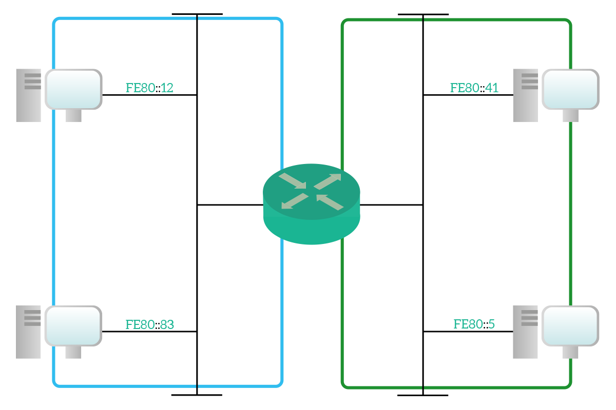
An IPv6 link-local address is an address that is valid only within the broadcast domain (it is local to it). This address is not routable, meaning that no router can have a route to it because it must be directly connected, and can be compared at a Layer 2 address, because it behaves the same way. We had a similar concept in IPv4, the APIPA address (169.254.0.0/16), which is valid only within the same network segment. The purpose of that, however, is revolutionary, and we will see it when talking about neighbor discovery. Since the link-local address is valid only within the broadcast domain, another device can have your address in another broadcast domain, or even the same device with NICs in different broadcast domains can have the same link-local address on each NIC. For link-local addresses, the entire fe80::/10 network prefixes is reserved, but only fe80::/64 can be assigned to interfaces. Generally speaking, for link-local addresses, the Interface ID part of the address is automatically generated with the EUI-64 technique (unless manually configured): the MAC address of the NIC is divided into two parts (OUI on the left, NIC specific on the right), then FFFE is added in between the two. For example, a NIC with MAC address 00:19:80:fd:48:de will have a EUI-64 of 001980FFFEfd48de, resulting in an IPv6 link-local address of fe80::0019:80ff:fefd:48:de/64.
Multicast
If with IPv6 we introduced the link-local address, we also removed the broadcast addresses: both the directed broadcast address and the standard broadcast address. However, we still need a way to send information to all nodes on the segment, so we cannot just get rid of the broadcast. Instead, we have to find different ways to do what broadcast did. And we completely replaced broadcasts by leveraging the concept of the multicast address. Just like IPv4, a multicast address is an address “subscribed” by multiple nodes: these nodes will be listening to that address. All multicast addresses, in IPv6, belong to the ff00::/8 prefix.
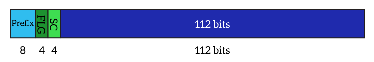
The structure of an IPv6 multicast address is dived into four groups of bits. Starting from the left, we have the network prefix (first 8 bits constant to ff), four bits of flags (FLG), and four bits of scope. The scope indicates where the multicast address is valid and, therefore, unique (e.g. an organization, the broadcast domain etc.). From the four bits available for flags, only three are used, as described below.
- Reserved – the first and most significant bit is not currently used, but reserved for future uses
- Rendezvous (R) – Set to one of the rendezvous point is embedded
- Prefix (P) – Set to one of the address is based on network-prefix information
- Transient (T) – Set to zero if this is a well-known multicast address, set to 1 if this is a dynamically assigned address
The value of the scope field (SC), can vary modifying the first part of the address, which reflects where the address is unique as follows.
ff02::– link-local, the multicast address is valid and unique within the link (broadcast domain)ff05::– site-local, the multicast address is valid and unique within the same site, location or building (inside a bigger context such as an enterprise)ff08::– organizational scope, the multicast address is valid and unique within the same organization, enterprise or companyff0e::– global scope, assigned by IANA and valid worldwideff01::– interface local, the multicast address is valid and unique within the same interface, traffic to that address do not even touch the network link but remain internal to the node, this is the equivalent of the loopback address of IPv4
The remaining 112 bits on the right actually compose the multicast address and, in the end, the structure of an IPv6 multicast address will be a lot like in the following picture.
There are really a lot of well-known IPv6 multicast addresses, but for the time being it is important that you remember only two of them, reported in the following table.
| Address | Scope | Description |
|---|---|---|
ff02::1 | Link | All nodes on the link. It effectively replaces a broadcast address. |
ff02::2 | Link | All routers on the link. |
IPv4 originally not supported multicast address, and this was an addon for this protocol. IPv6, instead, supports natively the concept of multicast, but as far as we have seen, it is almost identical to the concept of multicast we had in IPv4. And this is true for the multicast addresses we have seen until now, while there is a special category of multicast addresses that behaves in a different way: the solicited-node multicast address.
A solicited-node multicast address is a special multicast address subscribed by a single node. It is automatically created taking the last 24 bits of the IPv6 address of the interface and appending them to this fixed prefix: ff02:0:0:0:0:1:ff00::/104. As an example, the fe80::2aa:ff:fe28:9c5a link-local address will generate this ff02::1:ff28:9c5a solicited-node multicast address. Note that the last 24 bits correspond to the last 6 hexadecimal digits. What is the reason behind the development of such a strange address? What is the purpose of having a multicast address being listened to by a single node? With this address format, we achieve a very unique functionality. Back when we talked about Ethernet and Data Link layer, we learned that multicast addresses are treated as broadcast addresses by switches and layer 2 devices. With this multicast address, we can have our traffic treated as broadcast traffic from layer 2 devices, and as unicast traffic from layer 3 devices. The need for that will be explained later on in this article.
Anycast
IPv4 does not support the concept of anycast address natively, and in order to implement that with IP in version 4, we have to break the specifics of the protocol. With IPv6, this is different, because anycast is natively supported. An anycast address is between the concept of multicast and unicast address. To be more specific, it is actually a unicast address assigned to multiple devices around the world, and instead of identifying the device itself, it identifies the services it offers. This allows other devices to point to that services and reach the nearest device offering that service, without actually knowing what is the nearest device. This simplify the client (end-user device) configuration, but adds complexity in the routers in the path. The more the devices sharing the same anycast address are distant (in terms of routers in the path), the more complexity is added to the mix. This, however, allows a geographic distribution of services.
Unicast addresses
Unicast addresses in IPv6 are what they used to be in IPv4: they are assigned to a single interface and they identify it over the Internet. Even if we still have IPv6 site-local unicast addresses behaving like private IPv4 addresses, there is no need to multiplex multiple private addresses onto a single public address to save space: each device can be assigned with its own public address, we have plenty of addresses. This way, the addressing plan of an enterprise can be directly created with public addresses rather than with private ones.
Another revolution that IPv6 brings to the table is that multiple unicast addresses from the same prefix can be assigned to the same network interface. To that, you can add anycast addresses and a single link-local address (this is the one that you cannot have multiple instance of).
As of now, IANA is assigning addresses only from the 2000::/3 prefix, while the 2001:db8::/32 prefix is reserved for documentation purposes and may not be used in real-life environments.
Neighbor Discovery & Router Discovery
We already know that IPv6 is a whole new framework that is not only intended to replace its predecessors but also a lot of protocols that IPv4 relies on. Among them, there is the Address Resolution Protocol (ARP), which is used to map IPv4 addresses to MAC addresses. With IPv6, we can completely get rid of this protocol using a more efficient one, the Neighbor Discovery Protocol (NDP). NDP relies on the Internet Control Message Protocol version 6 (ICMPv6) packet to do its job.
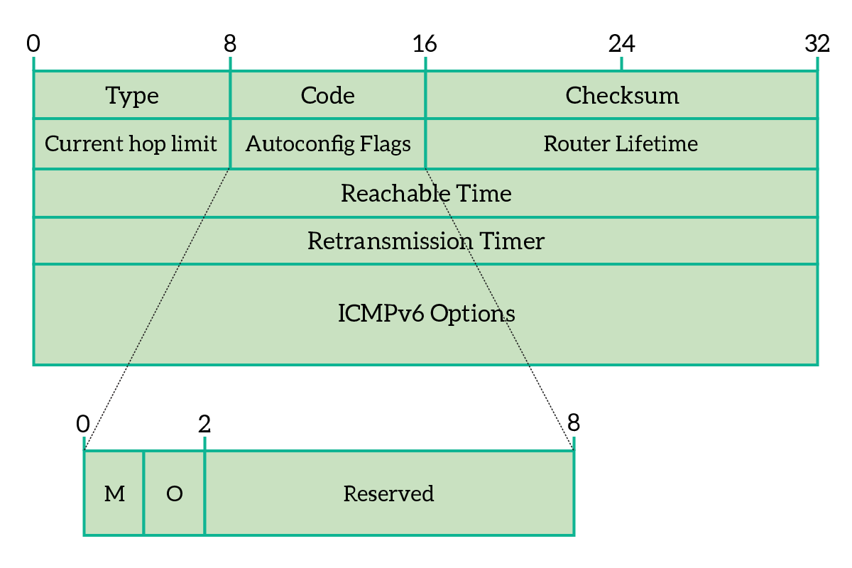
The ICMPv6 packet is a layer 3 PDU that is actually encapsulated into an IPv6 packet. Its structure is fairly simple, we have a Type field and a Code (or sub-type) field, a checksum to verify that everything was delivered correctly and then some room for ICMPv6 specific data, that vary according to the type and code. The following picture, as an example, shows the fields presented in Type 134 ICMPv6 packet.
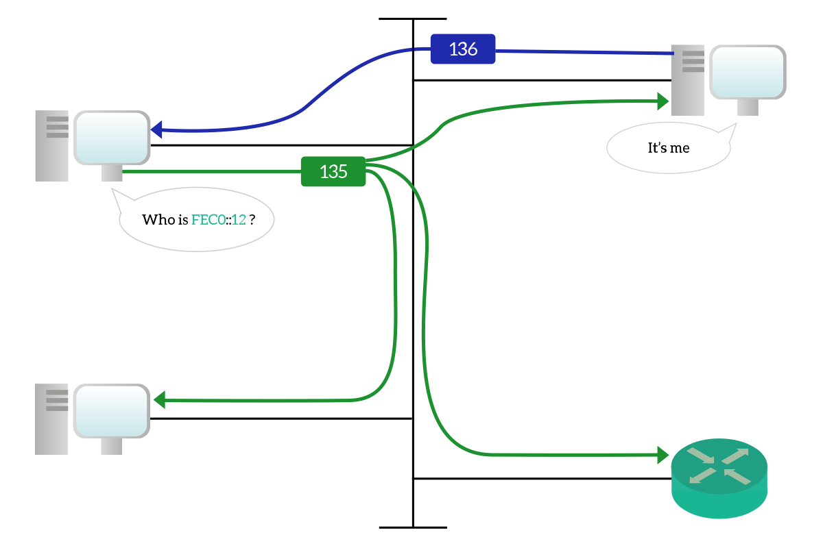
In the replacement of ARP, we use two different ICMPv6 packet types. The type 135 is used in replacement of ARP Requests, and the type 136 is used in replacement of ARP Replies, this is the process of Neighbor Discovery (ND). A node wants to communicate with another node on the same broadcast domain, but knows only the IPv6 unicast address of the destination, while the link-local and layer-2 address are still unknown. In order to obtain that information, the sender crafts an ICMPv6 packet with Type 135, known as Neighbor Solicitation (NS), and send it to the solicited-node multicast address of the target device. This way, layer 2 devices along the path will treat this packet as a broadcast, forwarding it to all devices. However, only the target device will be the one processing it. Then, the target node will craft a new ICMPv6 packet with Type 136, known as Neighbor Advertisement, to reply to the request with the information asked.
A similar process is put in place in order to find the default gateway for a broadcast domain. A client device sends an ICMPv6 packet with type set to 133 (Router Solicitation, RS) on bootup, looking for routers on the segment. This packet is sent to the all-routers multicast address ff02::2. Then, any router on the segment will reply to that with a type 134 (Router Advertisement, RA), containing the address of the router as well as other information that are useful for the client device to either obtain its IP address from a server or to automatically create its own (this last case known as Stateless Address Auto-Configuration, or SLAAC).
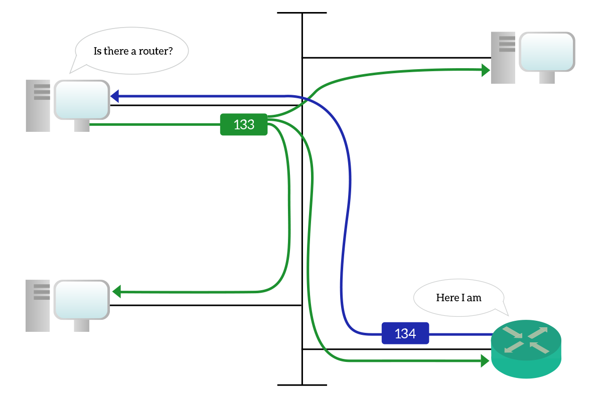
Router advertisements are sourced from link-local addresses and are generated in reply to solicitations and also periodically (every 200 seconds). When they are generated periodically, they are intended for all nodes on the segment (ff02::1 multicast address).
Migration from IPv4
We now know how beautiful IPv6 is, but replacing every hardware and software components in the world with something else supporting either both IPv4 and IPv6 or only IPv6 is just a dream, at least for the foreseeable future. Instead, migration will be (and is) a slow and long-lasting process, where IPv4 and IPv6 will be present together for some time. To facilitate that, several techniques have been developed to support the migration and interoperation of these two versions of the Internet Protocol.
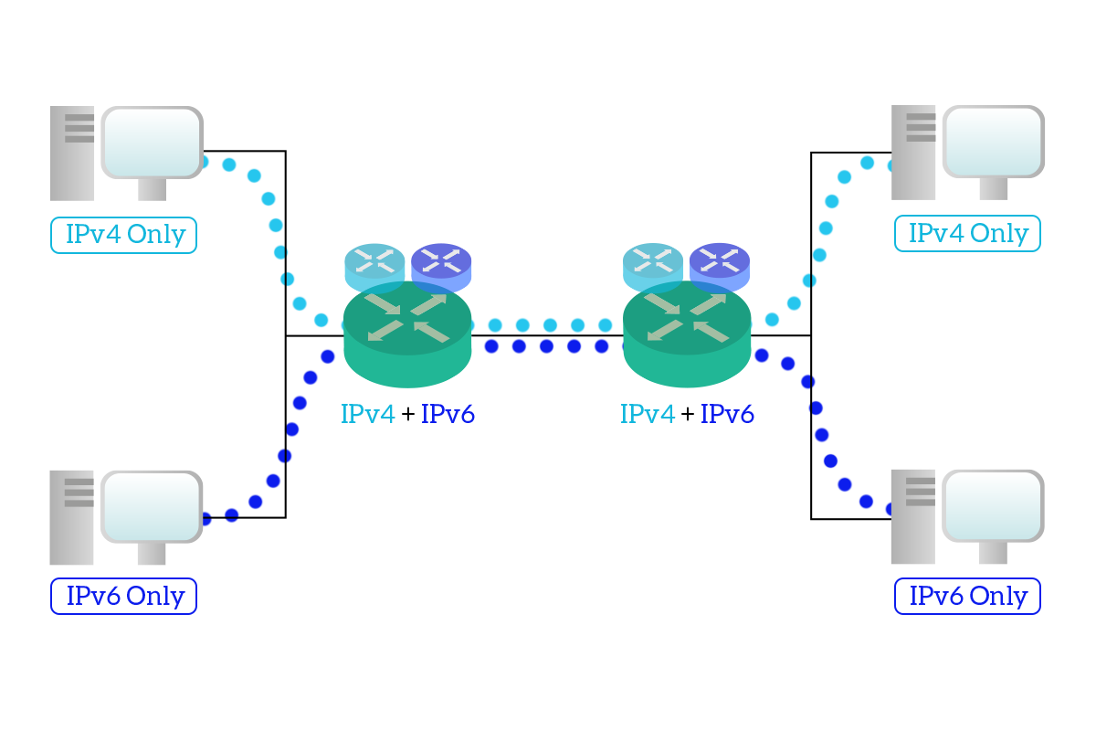
The first and easiest technique is known as Dual-Stack. This technique allows the migration from version 4 to version 6, but do not allow IPv4 devices to talk with IPv6 devices. The concept is pretty simple, as you might have guessed from the name: devices run two OSI stacks, one containing the IPv4 framework and one containing the IPv6 framework. This way, intermediary devices can forward and route both IPv6 and IPv4 traffic, but the logical IPv4 network remains separated from the logical IPv6 network. This means that a device speaking only IPv6 won’t be able to speak with another device speaking only IPv4. The majority of modern hardware components (clients, servers, routers) do support dual-stack.
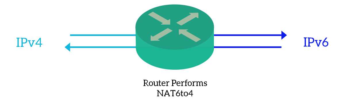
A great technique to allow devices from the older protocol to talk with devices with the new protocol is known as NAT6to4, which means Network Address translation “six to four”. The idea behind that is very simple, we fill the last 32 bits of a specific IPv6 prefix (2002::/16) with the 32 bits of the IPv4 address. Then, the traffic can be routed in the IPv6 only network. However, the IPv6 network has to be configured in such a way that supports routing inside that 2002::/16 prefix.
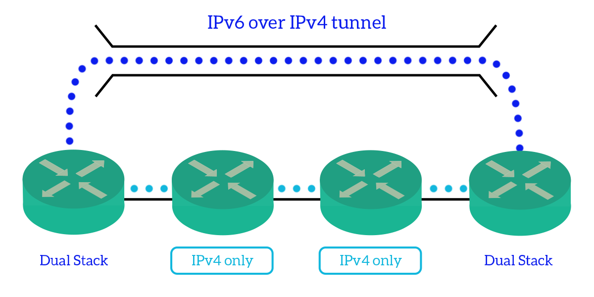
Finally, we have IPv6 over IPv4 tunneling. This is used to send information with IPv6, bridging over a network that supports IPv4 only. This allows the migration because IPv6 can spread over non-IPv6 areas, but not the interoperation because it has to be done by two dual-stack devices that maintain the two stacks divided. The IPv6 packet is encapsulated inside an IPv4 packet just like a Layer-4 datagram, then send over the IPv4-only network, targeting the destination dual-stack device. That device will get the IPv6 packet out of the IPv4 packet and continue the routing in another IPv6 domain.
All in all, with this article we presented the beauty of IPv6 starting from the flaws of IPv4. We now know what are the root causes behind the creation of this newer version of the Internet protocol, and we know what are the benefits it gives. We covered the addressing methods and type of addresses, the replacement it brings to the TCP/IP framework with Neighbor and Router Discovery, and finally, we treated some techniques used to allow the transition from the older protocol to the new protocol. With this solid knowledge of the network layer, spanning from IPv4 addressing and subnetting to IPv6, we are now ready to face the upper layers of the OSI stack, introducing the Transport layer and its amazing protocols, but this is for the next chapter of the CCNA Course.

