The data link layer is the one that allows the communication between two contiguous nodes, which are nodes having access to a common media (connected together either directly or via a shared media). Even if this could seem simple at a first glance, at this layer protocols start to get involved. At the data link layer a lot of crucial tasks have to be handled, such as the detection of interferences, the delivery to the correct node if more nodes share access to the same media or the rules that allow a device to talk on the media or to wait for its turn. In this article, we will cover all that, going even deeper to truly understand the data link layer.
Data link layer
We already know the role of the data link layer from the article about the OSI stack: allowing the communication between two contiguous devices. The physical layer has no intelligence built-in, it’s just about transforming bits into signals and vice versa, without knowing what these bits actually mean. Sitting on top of that, the data link layer controls the physical layer and it is the one knowing the meaning of these bits. Changing the point of view, the data link layer is also the one that allows the network layer to communicate seamlessly over a heterogeneous network. In other words, the network layer does not care about how data are put on the cable, nor if the media changes from wired to wireless, thanks to the data link layer that handles all of that autonomously.
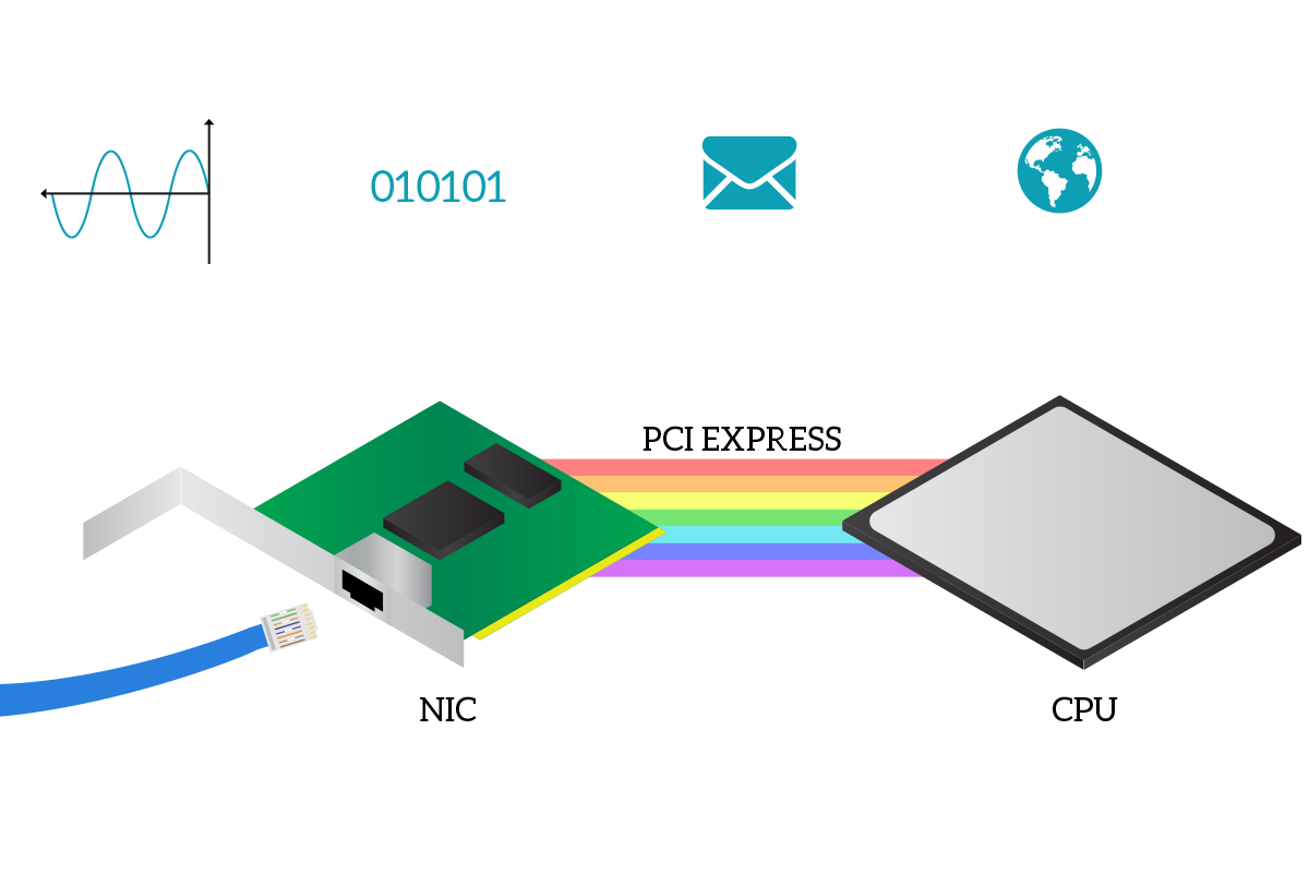
Until now, we just talked about concepts, but in the end, that data link layer has to be implemented somewhere. And it is present in any network device (otherwise the device wouldn’t be able to communicate at all), specifically in the Network Interface Card (NIC). The NIC is an internal module that you will find already embedded in almost any modern computer that allows the device to connect to the network. A NIC manages only one type of connection, so you are going to have a NIC for ethernet connection and a NIC for wireless connections. Intermediary network devices have several dozens of NICs because their role is to connect other devices together. Inside a computer, the NIC communicates with Central Processing Unit (CPU) of your PC thanks to the PCI Express bus, a channel of communication inside every computer that allows internal components to talk with each other. The CPU is the brain of the device, and it is the one handling application data: applications are executed inside the CPU. Each application will start with its own data (such as a web page in case of a web browser) and will break down that data in a network-layer form inside the CPU, then the CPU will pass this network-layer data to the NIC that will then manage the data link layer and then the transformation of that into signals (physical layer).
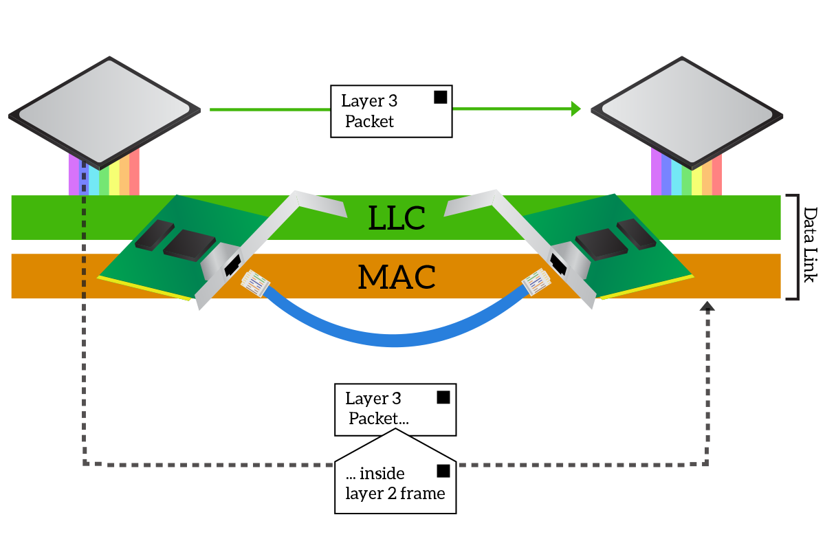
To intermediate the communication between the media and the CPU, the data-link layer is divided into two sub-layers. At the top, we have the Logical Link Control (LLC) layer, which is the one communicating with the CPU, while at the bottom we have the Media Access Control (MAC) layer, the one putting signals on the cable and reading them from it. Suppose we have to change from a cabled media to a wireless one, the part of the data link managing that media will have to change. With this structure, the MAC sublayer changes between different physical layers, but the LLC layer remains the same, providing a consistent interface for the network layer. This does not just allow the network layer to be truly and completely independent from the physical layer, but it allows the CPU and the application on it to imagine that they are talking directly to the application on the other device.
This is where the concept of encapsulation becomes extremely important. As we know, the information is originated by an application at the OSI layer 7, then it is passed down until it reaches the physical layer. Each time the data traverses a layer from top to bottom, that layer adds some pieces of information. These extra elements are then sent over the physical media and read from the other device, at the same layer: information added by the presentation layer from the sender will be read from the presentation layer on the receiver, information added at the session layer will be read at the session layer and so on. On the receiving device, these extra pieces of information are read from the intended layer and then removed before passing that data to the upper layer, so that in the end the receiving application will read just what the originating application sent. Encapsulation happens by adding some information at the beginning of data and, sometimes, at the end too. However, pieces of information are never added in the middle of the data. The application data, plus all the extra information added by layers, are called Protocol Data Unit (PDU), and the PDU of the presentation layer will be smaller than the PDU of the data link layer since at the data link layer more layers have added their information.
In order to make two applications things that they are talking directly, like if they were on the same computer, we heavily leverage encapsulation. In the CPU, we will prepare the data to be sent down to the network layer, then the CPU thinks that it has just sent the information this way. Instead, the NIC receives it and add to the Layer 3 PDU the information specific for the data link layer. The NIC of the receiving device will use that data link information to ensure that the data were not disrupted during the transfer and that data are actually destined to that device. If so, it will remove the data link layer information and pass the rest to the CPU, so that the receiving CPU will think it just received network data. The network layer PDU is called Packet, while the data-link layer PDU is called Frame, so the NIC will have to put packets into frames when sending and extrapolate packets from frames when receiving.
The pieces of information added at the data link layer enable all the features of this layer like delivery of information to the correct receiver over a shared media or interference detection. In the following section, we will start to see what these pieces of information are and how they are used.
Addressing at Layer 2
The most important thing done at OSI layer 2 is the delivery of information to the destination device. This is at the very basis of any communication, without that communication wouldn’t be possible at all. So, in order to deliver data to the correct destination device, we have to know where this device is, we have to know its address. And this is a lot like snail mail letters, the data link layer information is an envelope containing data from upper layers. Like snail mail delivery, we read the address on the envelope to know where the letter has to go.
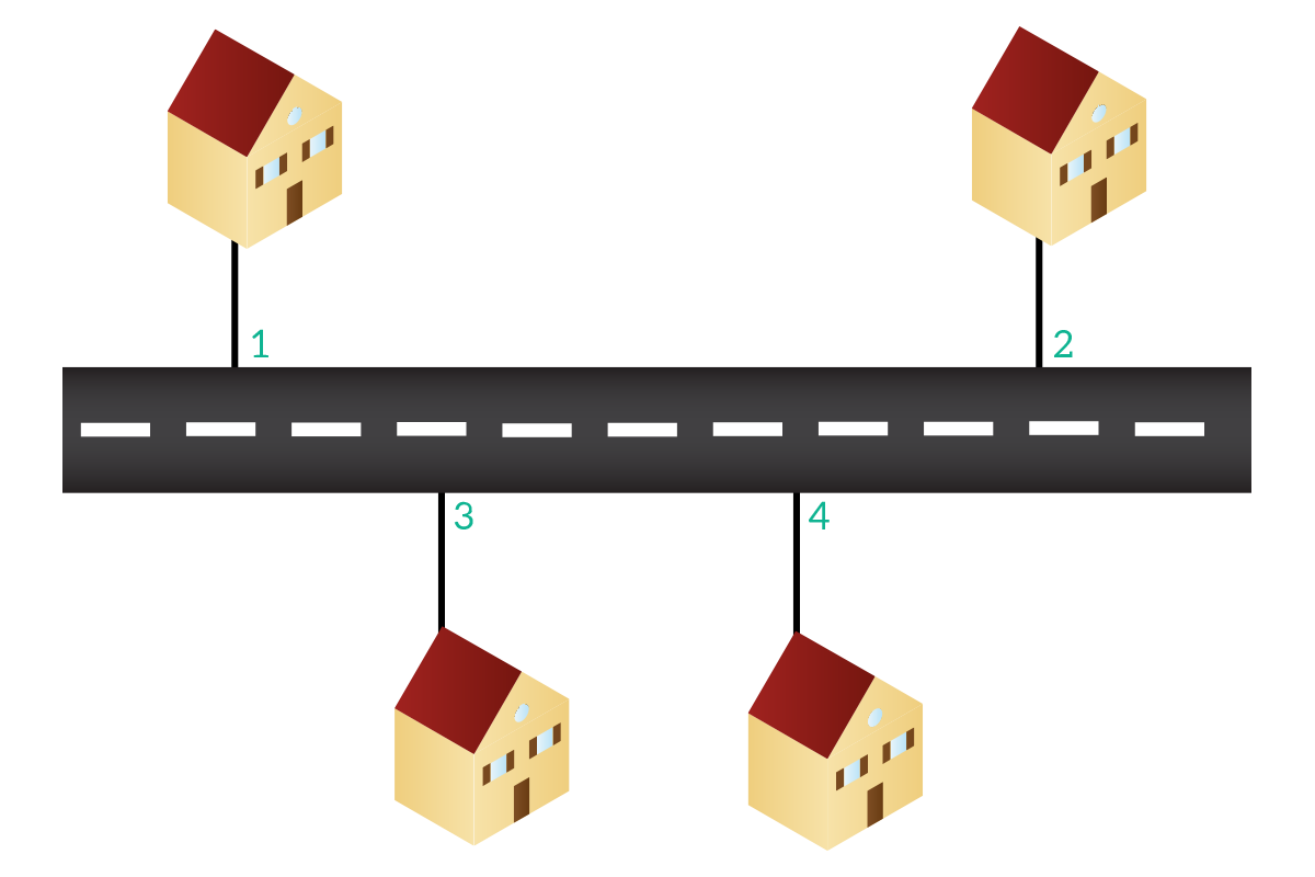
Networking is extremely similar to what we just explained. Like any house has its own address in reality, each device has its own address in networking. A device will have a Layer 2 address and a Layer 3 address, and then each application on that device will have a layer 4 address. For now, we will focus on the Layer 2 address.
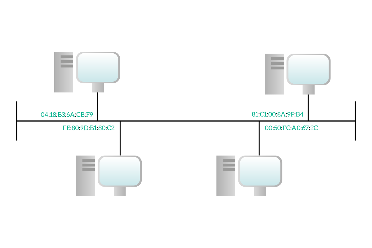
These strange codes you see in the picture are the Layer 2 addresses of the devices: the MAC addresses. A MAC address is long six bytes and it is represented in hexadecimal notation. If you are following the CCNA Course here at ICTShore.com you will know back from the binary math article what binary notation and decimal notation are (if not, I would encourage you to check it out). Hexadecimal notation is just like that: decimal notation is based on powers of ten, binary notation is based on powers of two and hexadecimal notation is based on powers of 16. You don’t need to know hexadecimal math as binary math, but it is handy to know the basics.
Each digit is worth 16 values, going from 0 to 9 and then from A to F. To represent 16 values in binary, we would need 4 bits, so a single hexadecimal digit will represent a nibble and two will represent a byte. Below, you will find a quick table useful for conversions.
| Decimal | Binary | Hexadecimal |
|---|---|---|
| 0 | 0000 | 0 |
| 1 | 0001 | 1 |
| 2 | 0010 | 2 |
| 3 | 0011 | 3 |
| 4 | 0100 | 4 |
| 5 | 0101 | 5 |
| 6 | 0110 | 6 |
| 7 | 0111 | 7 |
| 8 | 1000 | 8 |
| 9 | 1001 | 9 |
| 10 | 1010 | A |
| 11 | 1011 | B |
| 12 | 1100 | C |
| 13 | 1101 | D |
| 14 | 1110 | E |
| 15 | 1111 | F |
Again, hexadecimal notation is just a convention to represent MAC addresses in a more human-readable manner, but they are stored in binary as any other information. Let’s explore the MAC address anatomy in a little more detail.
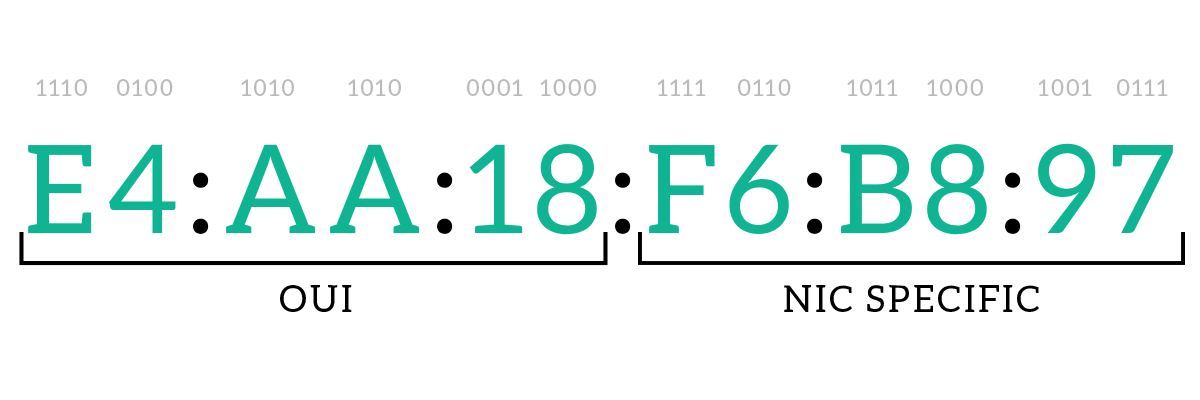
A MAC address is a layer 2 address that is assigned to any NIC, so a device with two NICs will have two different MAC addresses. It can be represented in different ways: in a dotted notation as in the picture, with a hyphen notation E4-AA-18-F6-B8-97, or with a dotted notation dividing for words e4aa.18f6.b897: both uppercase and lowercase are accepted, as long as in the same address you use only one of them (either all lowercase or all uppercase).
A MAC address identifies specifically that NIC, and it is unique: no duplicate exists in the world. The first three bytes (three pairs of digits) are called Organizationally Unique Identifier (OUI), and they are assigned to a company producing NICs. Then, when that company will produce NICs, it will assign the last three bytes of the MAC to the NIC. Large NIC producers such as Cisco have purchased several OUIs because they produce so many NICs that having just three bytes to define their unique identifier was not enough. Since the OUI is assigned to companies, we can understand from the MAC address of a device who was the manufacturer of its NIC, several tools exist to do just that and are available online for free, such as on the Wireshark site. If you are curious and want to try, on Windows, press Windows+R, type cmd and press enter. Then, type ipconfig /all and look for the “Physical address” list item.
The MAC address comes already installed in the NIC. It can be modified via software, but the original MAC on the NIC cannot be removed completely because it is hardcoded in the hardware, this is called the Burnt-in Address (BIA), because it cannot be removed. Using a MAC address different from the BIA is not a common practice and it generally involves malicious activities such as spoofing (trying to read traffic that was not intended for us).
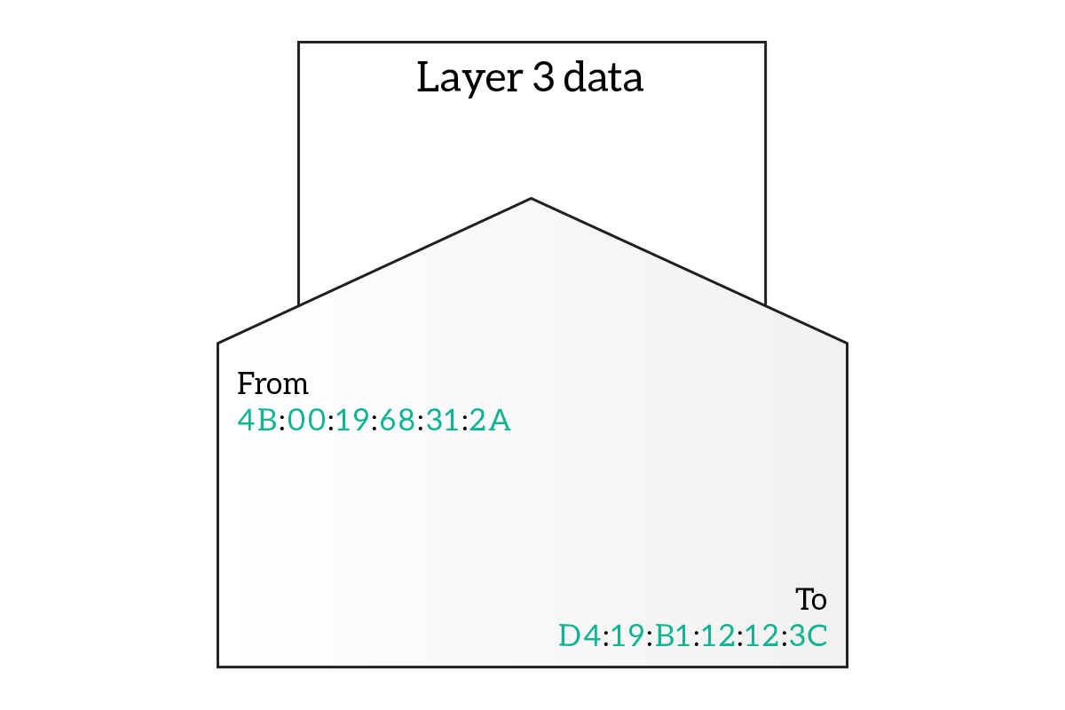
MAC addresses are the ones used to deliver the information to the correct destination device. The Data Link Frame containing layer 3 information will have on it the destination MAC address and the source MAC address. The delivery is based only on the destination MAC address, but the source MAC address from the destination device to know where to send the reply (note that this is not true for all devices).
Note: We explained that the MAC address is related to the NIC and not directly to the device, but from now on, just for simplicity, we will talk about it as if it were related also to the device.
Not all MAC addresses are made the same, three types exist: unicast, broadcast and multicast, and this is because these three types of addresses are related to three different types of data transmission, named exactly the same. Information is sourced always from a single device, but it can be destined to one or more devices.
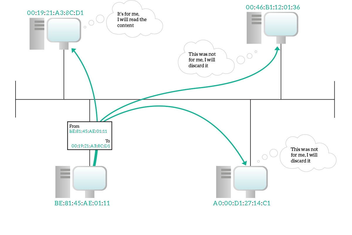
In a unicast transmission, information is destined to a specific device and only to it. A unicast address identifies specifically a single device. The unicast address of the source device will be written on the frame as source address, even for broadcast and multicast transmission (since the source device is just one). Even if the information is intended for a single destination device, on a shared media everyone can listen to everything. With the destination address written in the frame, each device listening can read the destination address and understand if the frame was actually for itself (and if so, continue the reading).
In a broadcast transmission, information is destined for every device connected to that shared media. A broadcast address indicates all destination, and only a single broadcast address exists: FF:FF:FF:FF:FF:FF. This is a special address that has no OUI. A broadcast frame will be generated from a single device as always, with the unicast address of that device specified as source address, and will have the broadcast address as the destination address. All devices on the media know that this is the broadcast address and will actively listen to the traffic sent to that address.

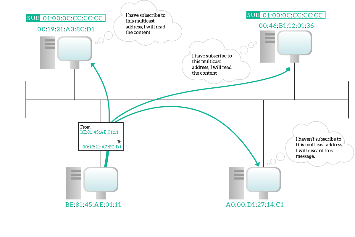
In a multicast transmission, information is destined to multiple devices connected to the shared media, but not all of them. As always, the source address in the frame is the unicast address of the sourcing device, but as the destination we have a special multicast address. A multicast address is any address that has the eighth bit starting from the left set to one. Ethernet network equipment will treat these frames just as broadcast frames so that they are delivered to all devices. Then, devices who subscribed to that multicast MAC address will actually read the whole frame, other devices will just discard it. Even if the technical term is “subscribe to a multicast address”, a device just have to be willing to listen, there is no central device that accept a subscription or something like that: devices decide autonomously which multicast traffic they should listen.
Now that we have an idea about how the layer 2 communication is possible, it is time to see how this really happens.
The Ethernet Frame
The Ethernet Frame is the envelope containing the information coming from the upper layers. We already know that it has to contain the source and destination MAC addresses, but it is not just that. Two different Ethernet Frames exist, Ethernet II which is the old legacy one, and the 802.3 frame which is the one used today.
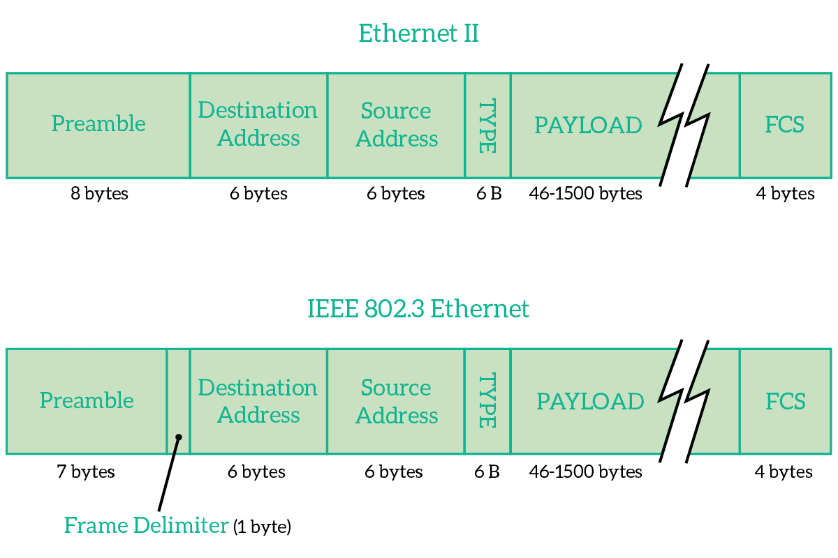
The frame is composed of three parts: the header, the payload and the FCS. The header is the set of fields that are companions to the transmission, that is just needed for the purpose of transmitting/receiving. The payload is the content from upper layers and the FCS is a field that allows the receiver to check if the message was disrupted over the transmission. The header is composed of the addresses and the type/length field.
Information has to be sent as a series of bits in sequence, so frames are just that. Moreover, the PDU from upper layers is put inside of that sequence. The first 8 bytes to be sent are essentially a preamble for both frames, they announce that something is coming so that receivers can get ready. The preamble has the role to allow the receiver to get ready for the frame that is coming and synchronize with the Phase Locking Loop technique. A preamble is basically a signal going up and down (1, then 0, then 1 again and so on). This preamble has been reduced from 8 to 7 bytes in the 802.3 version because it has to create some room for the Start Frame Delimiter. This was possible thanks to more modern PLLs that worked even on a 7 bytes transmission.
Then, we have the Start Frame Delimiter (SFD) in the 802.3 frame. This says to the receiver “Okay, now we are there. The next bit will be part of the frame, so read it”. This is very important because originally the destination device would have to listen to the preamble from the very first bit and count 8 bytes to understand where the message started. Now, with the SFD, the destination device does not have to count anymore, it is noticed from the sender when the message arrives using the SFD. This way, even if the destination device lost some of the preamble, it can always get the message if the PLL was so good to synchronize the clock in the preamble bytes that were listened from the destination device.
Then, in both frames, we have the Destination Address and Source Address. These are the MAC addresses of the intended receiver and sender device. The destination address comes first so that any device listening to the media can read it quickly and decide whether it should listen to the frame or not.
After the source address, in the Ethernet II frame, we have the Type field, technically called EtherType. This indicates which protocol is encapsulated inside that frame. Each protocol that can be encapsulated in the ethernet frame (generally network-layer protocols) has its own numeric identifier, that identifier is the content of this field. Knowing the type of content, the receiving device knows how long the encapsulated content is, and therefore can read the correct number of bytes. This approach, however, did not support flexibility: receiver device couldn’t be able to handle variable-length messages, and complex mechanisms were put in place to allow variable-length messages. With the newer 802.3 frame, a simpler way of doing this was needed, so we changed that field in Length. This just tells the receiving device how many bytes is the encapsulated content long.
After the Type/Length field, we encounter the payload. This is just the encapsulated content, information coming from the upper layers of the OSI stack.
At the end of the frame, we find the Frame Checksum (FCS). This is the field used to verify that the frame was delivered correctly: it is a summary of the frame. The receiving device create that summary again starting from the frame itself and then compare the summary it created with the summary it received. If they are the same, the message was not disrupted and will be processed, if they differ it means that something went wrong so the frame will be discarded. Note that if the frame is discarded the sending device will not be notified and that you can create the summary from the frame, but not vice versa.
Now, the 802.3 frame is used on ethernet-cable connection. However, this is not the only connection available today. Another heavily used connection is the Wi-Fi, which has its own frame.
Layer 2 in the air
The Wi-Fi frame is defined in the IEEE 802.11 standard. It is much more complex than the ethernet frame because transmission over the air involves much more items. Before moving to the frame, we must know the logic behind the transmission. On a wired shared media, who talks when is managed by the CSMA/CD algorithm, that we explained in the article about network topologies. On a wireless network, the algorithm is slightly different, it is the CSMA/CA.
CSMA/CA stands for Carrier Sense Multiple Access Collision Avoidance, and this is exactly what it does: devices using this algorithm try to prevent collision before they happen because collision detection cannot be applied in this case. The fact that CSMA/CD is not suitable in this case is due to the fact that devices always talk to an Access Point, which is the central device. The Access Point can listen to a single device per time, and if your device “see” the access point it does not necessarily mean that you see all the devices seen by the access point (maybe the AP is on top of an hill, you can see it but you can see devices on the other side of the hill). So, if the collision happens between the AP and another device trying to talk (ignoring that you were already talking), it cannot be detected correctly. This is why it has to be avoided beforehand.
A device wanting to transmit something wait for the channel to be idle: if the channel is busy, the device waits for a random back-off time. Once the channel is idle, in CSMA/CD we would just transmit. Instead, in CSMA/CA, the device sends a Request to Send (RTS) message to the Access Point and then wait for a short amount of time. If within that time the device receives the Clear to Send (CTS) message from the Access Point, then it goes on with the transmission, otherwise it considers the channel busy and the device waits again for the back-off random time, then try again by sending the RTS (or wait before sending it if it sense that the channel got busy). In this process, we assume that the Access Point has visibility to all nodes, this is the reason we ask to it if we can transmit. If you are a programmer or know a little about it, you will find interesting the following pseudo-code for the CSMA/CA.
while ( true )
  if ( hasSomethingToTransmit() )
    while ( mediaIsBusy() );
      sendRTS()
      wait( aShortTime )
      if ( receivedCTS() )
        transmit()
This mechanism put in place with the CSMA/CA algorithm also possible thanks to the implementation of 802.11 as frame. In wired Ethernet, we have just data frames: frames carrying information originated in upper layers, but in Wi-Fi, we also need management and control frames, frames that maintain and monitor the communication. For example, when you look for a free Wi-Fi hotspot and you see a lot of networks on your smartphones, you see them because Access Points in that network sent you a Beacon frame, a frame to notify you the existence of the network. For the purpose of this article, we will see only the 802.11 data frame. Fortunately, you don’t need to know the 802.11 frame for the CCNA certification, nor for CCNA-level jobs. However, it may be interesting to have a look on it.
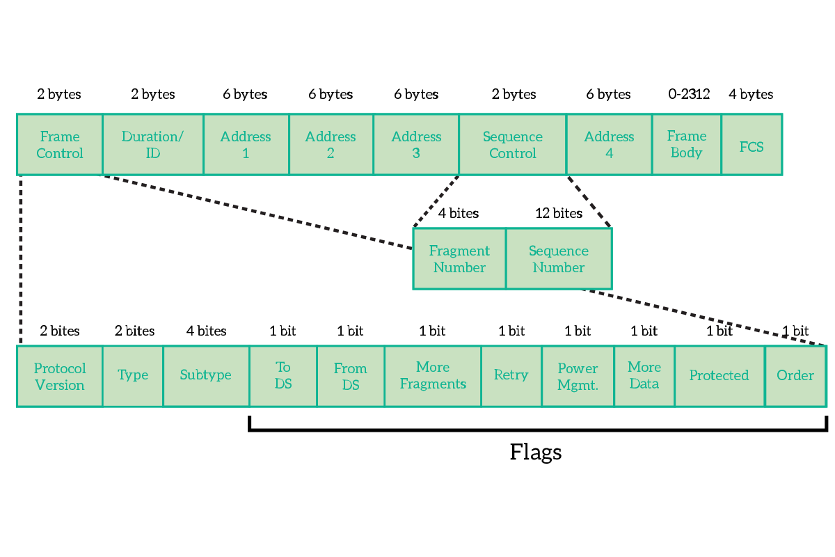
The first two bytes of the frame are dedicated to Frame Control. This is not a single field, but instead a combination of smaller fields and flags, where a flag is a field long a single bit and that can therefore be set only to true (1) or false (0). In the frame control, we have the following fields.
- Protocol version – Version of the protocol 802.11, generally 0
- Type – Type of the frame, such as data, control or management
- Subtype – Used together with the type to identify exactly what type of frame this frame is
- ToDS – True if the frame is headed to a Distribution System
- FromDS – True if the frame is coming from a Distribution System
- More Fragments – True if the data from the upper layers have been divided into multiple frame (and the decision was taken at layer 2)
- Retry – True if this is a retransmission of a frame
- Power Management – Indicates what will be the state of the power of the sender after the transmission
- More Data – True if another frame is coming, used by APs to facilitate the reception for clients that are in power-saving mode
- Protected Frame – True if the frame in encrypted (using Wi-Fi security such as WEP or WPA)
- Order – set if the “strict ordering” delivery is used
Then we have the Duration and up to 4 addresses, where Address 1 is the receiver, Address 2 is the transmitter and Address 3 is used for filtering purpose by the receiver. Before the fourth address, we have the Sequence Control, that is used to control the order of frames and eliminate duplicates. After the fourth address, we have the content coming from the upper OSI layers.
The Switch
The switch is the king device at the Data Link layer. It is a network device that has generally 8, 12, 24, or 48 ports (NICs) used to connect together computers and end devices. For example, will find a switch connecting all the workstation of an office. It is the modern successor of the hub and brings several improvements to the table. Before talking about that, we must first understand two concepts, the collision and the broadcast domain.
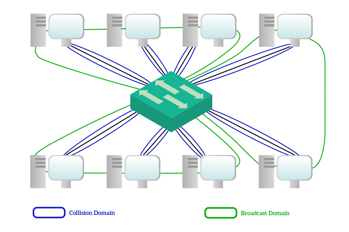
The collision domain is the set of devices that will hear a unicast message sourced by one of them. With a hub with four devices connected, when any of this four devices sent a unicast message to one of the other three, all the other three had to hear the message, even if it wasn’t for them. A broadcast domain, instead, is the set of devices that will hear a broadcast message source by one of them.
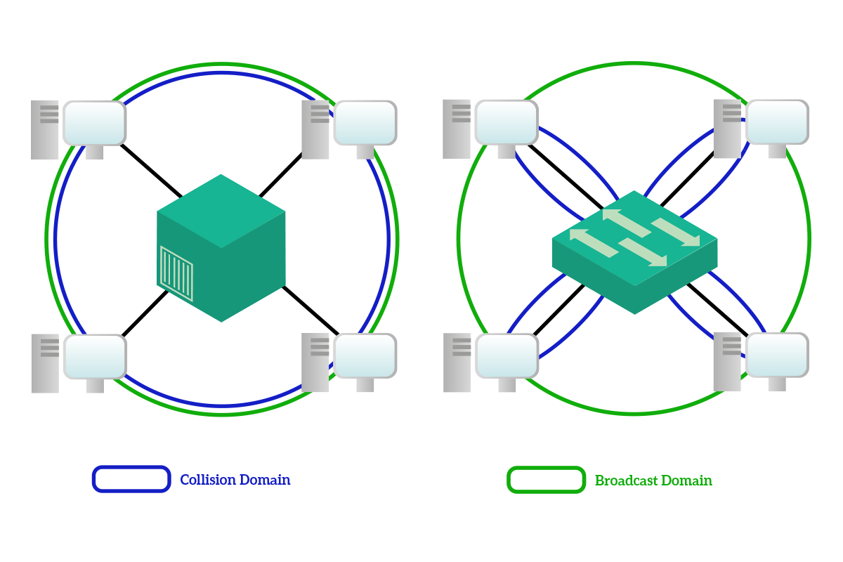
The most important improvement that the switch brings to the table is the collision domain segmentation: with a switch, unicast messages are delivered only to the intended receiver, so the collision domain that with the hub would have involved all the devices, with the switch is limited between the device and the switch itself. Broadcast domains, instead, are not limited: all devices connected to a switch will hear the broadcast sourced by any of them, and this is a wanted behavior. Also, note that the multicast traffic is treated as a broadcast and sent to all devices except the source from the switch. This is because the switch cannot know to which multicast address computers have subscribed.
To segment collision domains, the switch has to do some kind of thinking, compared to the hub that was just limited to electrically replicate the signal to all other devices. That thinking process is implemented with the MAC address table. This is a table stored in the switch memory and associate MAC addresses of connected devices to the port on the switch where these devices are connected.
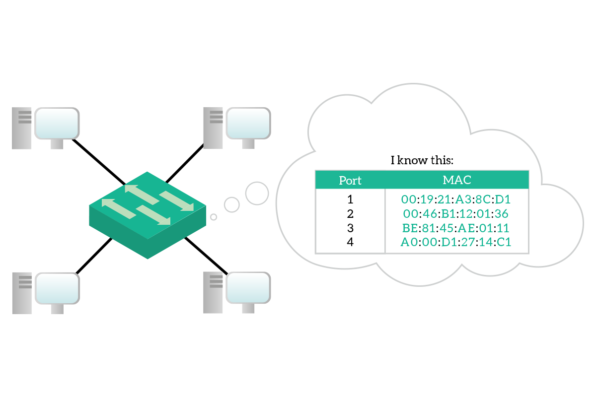
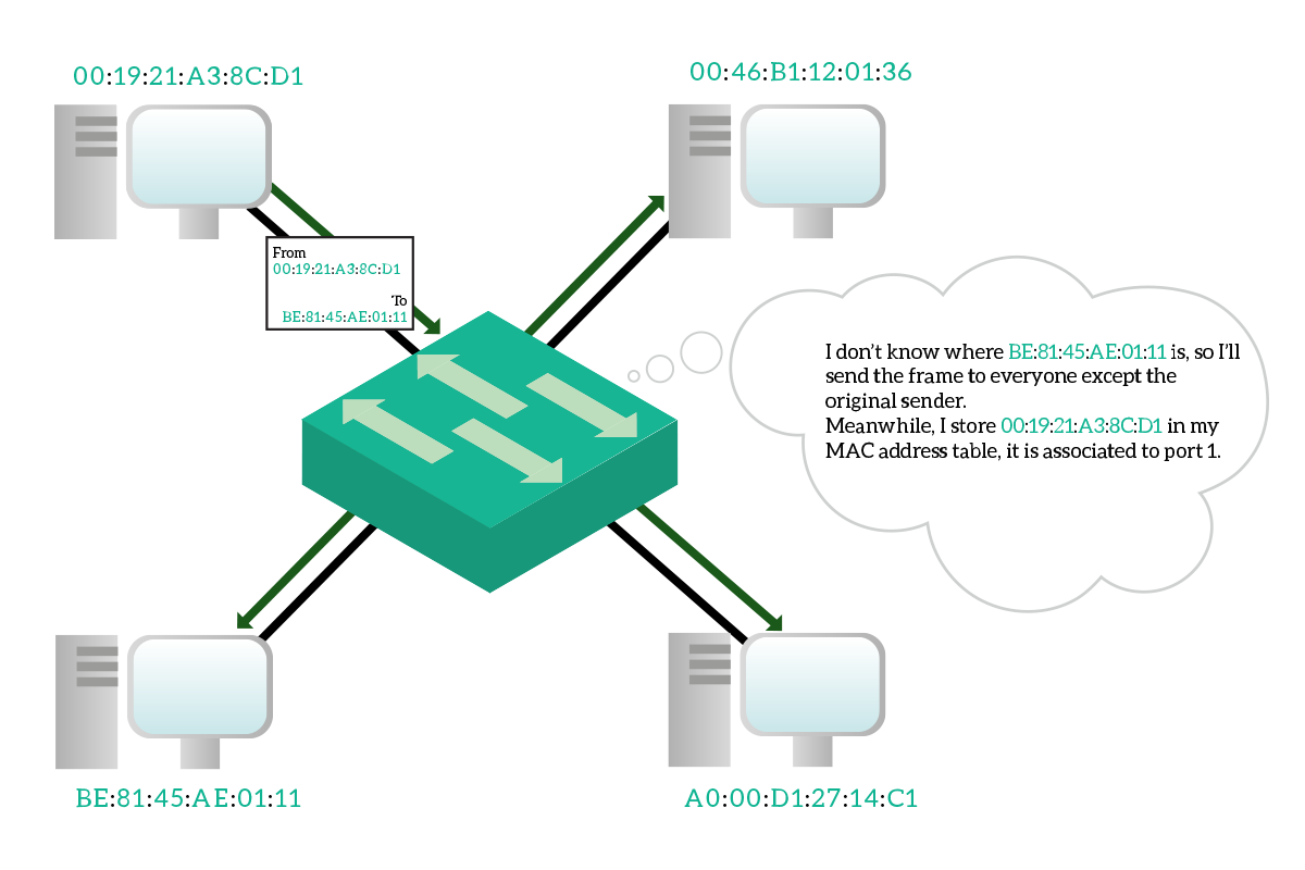
However, this MAC address table has to be dynamic: you cannot purchase a switch with a MAC address table already filled simply because the manufacturer cannot know which devices are you going to connect to that switch. More than that, it has to be very dynamic because you may un-plug a device to plug-in another one, and the switch has to know that you made that change. Fortunately, this table is maintained and updated dynamically by the switch. Every time the switch is powered on, it starts with an empty MAC address table, and it will populate it as soon as traffic started to flow. Every time the switch receives a frame, check the destination address and source address. If the switch knows where the destination address is connected, it will send the frame only out that port. If the switch does not know where to which port the destination address is connected, instead, it will send the frame out of all ports except the one where it received the frame. Meanwhile, it associate the source address to the port where it received the frame.
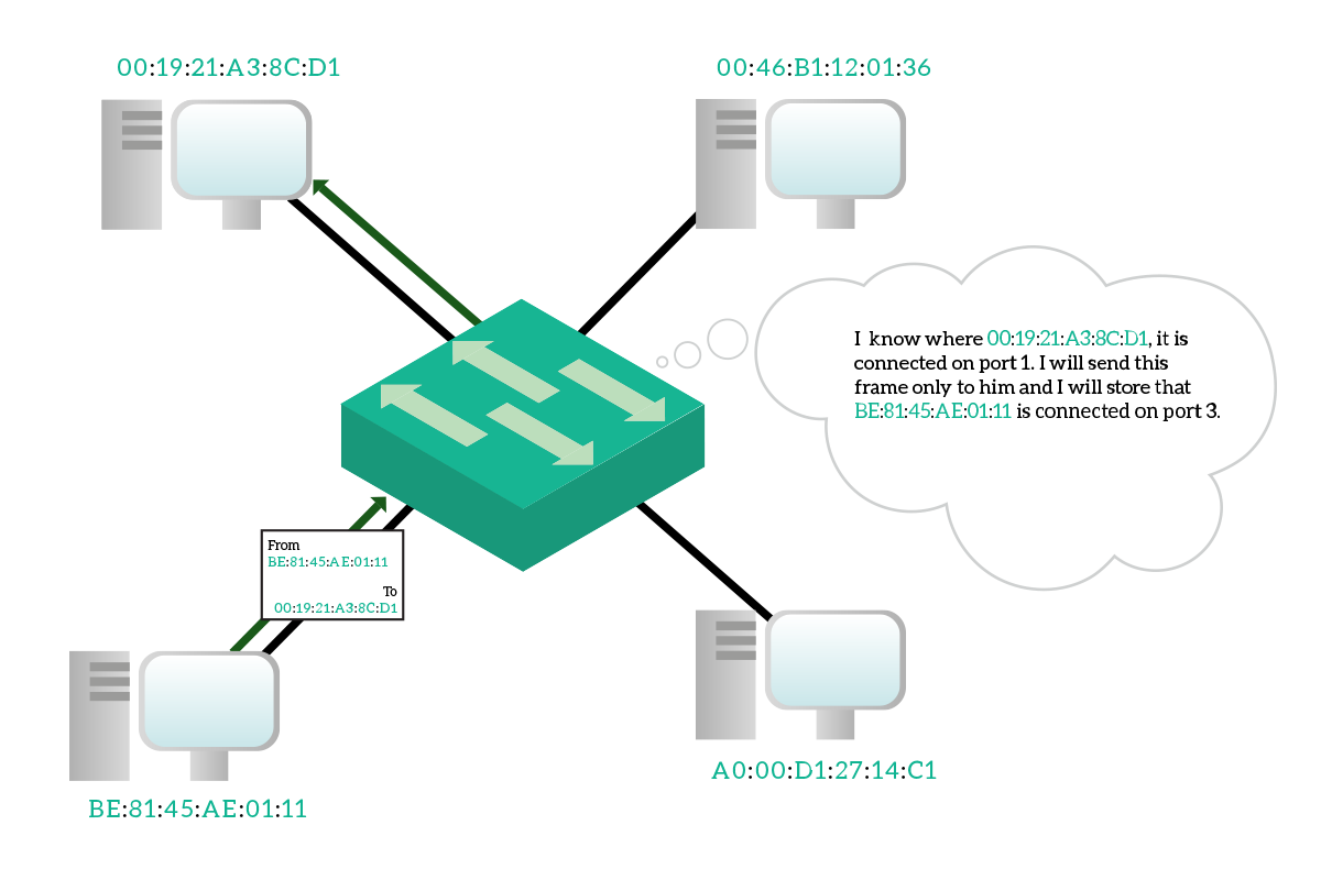
Hopefully, the destination device will reply back. When the reply message is received from the switch, it will check again the destination address and since it knows where this device is, it will send out that device only to that specific port. It will also check the source address, learning a new binding between the MAC address and the port. The communication between these two devices, from now on, won’t flood traffic to other devices because the switch knows where they are connected.
This enables full-duplex transmission, because you can send and receive simultaneously (using different pairs of the inner wires of the ethernet cable) since no collision happens anymore. This has been a very important improvement in networking, but it is not the only thing that a switch can do.
The switch has the possibility to work in two different ways, cut through and store and forward. With cut through, as soon as the switch reads the destination address it starts to send the frame out of the destination port (or ports). Instead, with the store and forward technique, the switch will listen to the whole message buffering it, then it will check the FCS to see if it was disrupted and only if it is a good frame it will send it out of the destination port (or ports). Switches work generally in store and forward mode since the delay is so small that it is not significant with the speed of modern networks.
Another cool feature of modern switches is Virtual Local Area Networks (VLANs). Basically, you can configure a switch to group its port in groups, where each group will be a broadcast domain. Broadcast traffic will spread only between ports inside the same group and with ports in a different group. In other words, you use a single switch to create multiple virtual switches.
Even considering everything that a switch brings to the table, switches were not immediately adopted when they were first invented. This is because of the high cost they had and because technology requirements weren’t so tight to need a bandwidth so high as it is today. But this is not the only reason, originally switches used to do their job in software, so all the traffic was processed by the CPU and this reduced the speed. Modern switches work with Application-Specific Integrated Circuits (ASICs), hardware components that do some very specific tasks extremely fast. With some specific ASICs, modern switches are able to maintain full-duplex transmission at wire-speed (like if the two end-devices were directly connected).
Nowadays, we cannot imagine a network without switches. And now, with the knowledge we developed about the Data Link layer, we have the tools to understand the reasons. More than that, we have the tools to truly understand Network Layer concepts, as we will do in later articles.

