
IPv4, simply known as IP, is the king protocol in the network world. It is the one used to deliver information anywhere on the Internet, from Hawaii to Siberia, from China to Scotland. In our globalized world, you need to speak English no matter where are you from. In the Internet world, you need to speak IP, no matter where are you from. In this article, we will explore the structure and functionalities of this protocol, understanding its features and benefits that make it the king of the hill, the one that makes Internet work, worldwide. With that, we will learn IPv4 addressing, introducing the knowledge needed to plan and design a network.
Note: to fully understand this article, you should have a basic knowledge of the OSI stack and of its lower layers (physical and data link). In case you are unfamiliar with them, check out our CCNA course’s articles – which includes this article too! -, you will find all the information you need.
IPv4 Addressing basics: Addresses and subnets
We already introduced the concept of addresses when we explained the data link layer in the previous article, and the concept is similar in some ways and different in some others. A data link-layer address is known only between contiguous devices (devices on the same broadcast domain), while a network address is known also outside of the broadcast domain and potentially globally. Be aware that any device will have an address at all layers, so it will have a data link layer address and a network layer address, with the first being a physical one and the second being a logical one. This network layer address is logical because it is not embedded in the device like a MAC address, but instead, it is assigned to the device. It can be configured by the administrator, or it can be obtained automatically, depending on the infrastructure.
We can compare a network-layer address to a global address you write on a post-card or on a letter. You are going to write the country, the city, the zip code, the street, and the civic number on your envelope. All of these pieces of information combined create the address itself, which is strictly dependant on the location: two different countries will have different addresses. If you move from a country to another, you will have a different address, and if a device moves from a portion of the network to another it will have a different address. Normally, we write addresses on an envelope starting from the most specific information (like the name of the person we are writing to) and we add in the following rows more generic information (the street, the city, the country). This however is counterintuitive, it has much more sense to go from the most generic information to the most specific one. This is what we do in networking: if we were to apply the same concept to our mailing system, it would look a lot like the following picture.
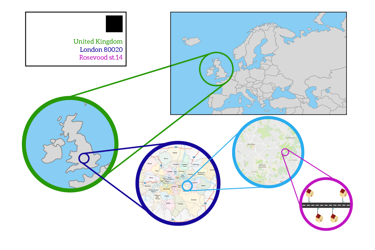
In snail mail, we developed a geographical addressing system to facilitate the exchange of letters. For the same reason, we tried to apply a similar approach to networking. This idea has not been applied at 100% with IPv4 due to practical reasons, so two devices geographically distant won’t have similar addresses generally, but it could happen from time to time. Instead of realizing a perfect geographical addressing system, we realized a perfect logical addressing system: networks are divided not by geographic position most of the time, but because of their logical features and roles in the global network. With that in mind, we are ready to face what IPv4 is.
IPv4 (expanded to IP version four) is the fourth version of the IP, which stands for Internet Protocol, and since it is the most used version at the moment, it is simply known as IP. It is a free protocol, and due to its features and its flexibility, it gradually replaced all the legacy proprietary protocols that were operating at the network layer, such as AppleTalk, IPX, or Xerox Network Systems (XNS). The IPv4 is described in detail in the RFC 791, an online document that highlights all the specifics of this protocol so that in case you are creating a new device or software that has to work with IPv4 you know how it works. IPv4 comes from a set of studies of packet-switched networks starting in 1974 and was officially released in 1978.
As any networking protocol, IPv4 works with two key elements: information sent alongside data to other devices, and addresses. Basically, each device has an address assigned (or multiple addresses in special cases), just like each home has an address. Data coming from upper layers are put in a virtual envelope having a source and destination IP address written on it. Intermediary devices will check that envelope to send that information, technically known as Protocol Data Unit (PDU), to the correct destination device. A network-layer PDU is known as Packet.
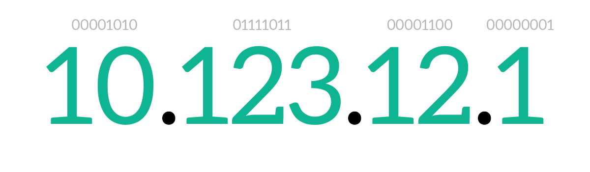
Before explaining the structure of an IP packet, we should explain how are IP addresses made and how do they work. An IPv4 address is 4 bytes long (32 bits). To represent it in a more readable fashion, we convert each byte in decimal notation and we write it like that, dividing each byte’s decimal value from the next one with a dot. This is known as IP dotted notation, and it is actually the only accepted way to write an IP address. Just like any address at any level, remember that representing it in decimal notation is just to make it readable: computers always store and process addresses in bits. Given that, the bits on the left are more generic than the bits on the right: this means that the bits on the left correspond to the country in a postal address, while the ones on the right to the civic number. From left to right, we go from generic to specific.
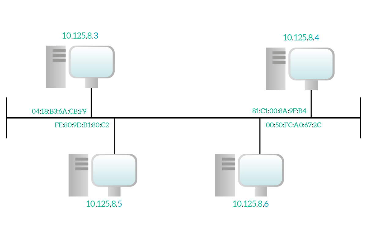
Contiguous houses have almost the same address, it is only the civic number the one that changes between one and the other. The same concept applies to network devices and IP addresses. Unlike MAC addresses, which are independent of the location of the device, IP addresses of contiguous devices will have the first part equal, and the bits on the right changing from a device to another, just like civic numbers.
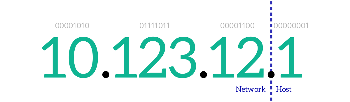
From that, we can understand that the first part of an IP address can be compared to the combination of country, zip code, and street in a postal address. The last portion on the right, instead, can be compared to the civic number. In networking terms, the first part is known as Network ID, and the last part (the “civic number”) is known as Host ID, where with “host” we mean device. With “network”, in this case, we mean the subnet, which is a group of contiguous devices that share the same broadcast domain. In other words, what is a subnet at the network layer is a broadcast domain at the data link layer, and vice versa.
Classful and classless addressing
The next question is almost automatic: how can we identify the Network ID and the Host ID portions in an IP address? It is extremely important to know where a portion ends and where the other starts. Originally, we used a technique called classful addressing, which defines the size of the Network ID portion based on the first bits in the IP addresses. Based on the first bits in the IP address, we divided IP addresses into five classes (from A to E). Addresses in classes A, B, and C are “normal” addresses that can be assigned to devices. Addresses in class D are special multicast addresses, used to reach multiple devices, while class E is used for experimental addresses. If the first bit is 0, then the address is a class A address, with the network portion ending on the eighth bit. If the first bits are 10, then we have a class B, if they are 110 we have a class C and so on. Take a look at the following picture representing all the classes.

The more bits we have in the Network ID portion, the more different networks we can have. On the other hand, the more the Network ID portion grows, the smaller the Host ID portion gets. Because of that, we will have a few Network IDs in class A, with a lot of hosts in each of them. In class C, instead, we will have many more Network IDs, but with fewer hosts in each network. The following table highlights just that.
| Class | Range | Network Space | Host Space | Networks Available | Hosts Available |
|---|---|---|---|---|---|
| A | 1.0.0.0 to 27.255.255.255 | 7 bits | 24 bits | 128 | 16,777,216 |
| B | 128.0.0.0 to 191.255.255.255 | 14 bits | 16 bits | 16,384 | 65,536 |
| C | 192.0.0.0 to 233.255.255.255 | 21 bits | 8 bits | 2,097,152 | 256 |
| D | 224.0.0.0 to 239.255.255.255 | – | – | – | – |
| E | 240.0.0.0 to 255.255.255.254 | – | – | – | – |
Classful addressing is a solution, and it works, but it is not always so practical. Let’s say you have a network where you plan to connect at most 10 devices, you should use a class C network which has space for up to 256 hosts. The remaining space (246 hosts) is wasted because you aren’t going to use it but since you purchased it nobody else will be able to use it. If you have to connect 257 hosts, you will need a class B network, which has room for 65 thousand devices, wasting even more space. Totally, we have 4’294’967’296 possible IPv4 addresses in the entire world (32 bits, 232 equals 4 billion). Four billion addresses may seem a lot, even if we remove multicast addresses and experimental addresses we still have a huge number of hosts, but no matter how huge it is, it won’t be enough. We have more devices connected to the Internet that it is hard to make them work with only four billion addresses, so no waste is acceptable here. To increase flexibility and meet that need, classless addressing has been released. In this case, the Network ID portion size is not determined by the first bit of the IP address, but instead from a companion element of the IP address, the subnet mask. The subnet mask is another field 32-bits long which tells where the network ID portion ends. While in an IP address you can have any bit combination you want, in a subnet mask 1 can be followed by another 1 or a 0, while a 0 can be followed only by another 0. This way, you will end up with all 1 on the left and all 0 on the right. Then, you combine the IP address with the subnet mask: where the subnet mask is 1, the respective bit in the IP address will be counted as part of the Network ID, where the subnet mask is 0, the respective bit in the IP address will be counted as part of the Host ID.
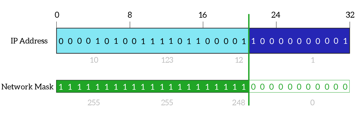
All modern networks work with classless addressing, it is the reason why we didn’t run out of IPv4 addresses back in the ’90s. However, be aware that the subnet mask is never sent in an IP packet. Instead, it is a value stored on each PC: each device will know its subnet mask so when it wants to send a packet to any IP it will compare that destination IP against the combination of its own IP and subnet mask to see if that destination is part of your subnet or not. Then, the packet will exit the device with source and destination specified, but without subnet masks.
We know that the majority of IP addresses are unicast and that the ones from 224.0.0.o to 239.255.255.255 multicast addresses. What about broadcast then? Just like at the data link layer, we have broadcast addresses at the network layer too. More than that, with IPv4 we have two types of broadcast addresses: standard broadcast and directed broadcast.
The standard broadcast address is 255.255.255.255, and it represents all nodes in the same subnet, no matter which subnet. It perfectly corresponds to the data link layer address FF:FF:FF:FF:FF:FF, more than that: a packet destined to a standard network broadcast will be put in a frame with that broadcast MAC address as the destination. Note that if we were to write this type of broadcast address in binary it would result in all 1.
The other type of broadcast for IPv4 is called directed broadcast, and it is the one to use if you want to reach all nodes in a specific subnet (which is not your subnet). In this case, there is not a single specific broadcast address, that address has to be calculated. To do that, you have to identify the Host ID portion of your address and put all of its bits to 1, this way you will obtain the directed broadcast address for your subnet. For example, if you work with a subnet 10.1.1.0 and a mask of 255.255.255.0, you know that the last byte is the Host ID portion, so the directed broadcast address will be 10.1.1.255. Once that packet with that destination reaches the target subnet, it will be converted into a standard broadcast. It is worth mentioning that the only ones to know that this address is a directed broadcast addresses are the source device and the devices in the target subnet. The source device must know that because it is generating traffic to that destination for a reason (at least we hope it is!), while the devices in the target subnet know that because they can combine it with their subnet mask and find out that this is broadcast. All other intermediary devices in the path between source and destination do not have the subnet mask of the destination, and they cannot distinguish it from a normal unicast address. However, this type of traffic is generally blocked from the edge device of the target network (the device connecting that network to the outside world), because it could be malicious. If for some reason we need that traffic, we should enable it on our edge device.
The IP Packet
As we should know, each OSI layer the information traverses going down some extra information is added. The network layer makes no exception, and the IP has its own packet. Mainly, it is used to define the source and destination IP addresses, but it does more than that. Let’s have a look at the packet.
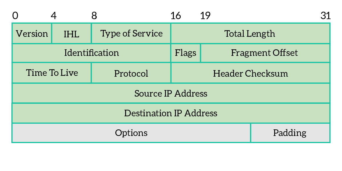
As we understand from the picture, the IPv4 packet is not simply about source and destination IP addresses. Instead, some extra information completes the scene. As any PDU, there is a header and a body/content. Information is added in the header part, while the body is just the content coming from the upper layers. Let’s explain what’s the role of each field in the header.
- Version – Indicates the version of the IP protocol, and it is always set to 4 for IPv4
- Internet Header Length (IHL) – Specify the size of the IP packet header, because it may vary depending on the options that are added
- Differentiated Services Code Point (DSCP) – Used in new technologies that require real-time streaming, such as VoIP
- Explicit Congestion Notification (ECN) – This field allows the two devices communicating to notify one another of network congestion before they have to drop packets
- Total length – The total length of the IP packet, including data, in bytes
- Identification – This field is used to identify IP packets of the same flow
- Flags – three-bits field, composed of three different flags, as explained below
- Reserved for future use, must be set to 0
- DF (Don’t Fragment) – this packet cannot be broken into multiple smaller packets, in case that packet has to go through a media/link that supports only smaller packets, it will be dropped
- MF (More Fragments) – set to 1 if this packet is the result of fragmentation, and another fragment is coming after this one
- Fragment offset – in case the packet is fragmented, it tells which byte of the original non-fragmented packet corresponds to the first byte of this packet, in a non-fragmented packet or in the first of the fragments it is 0, because the first byte of the current packet corresponds to the first byte of the original packet, so there is no offset
- Time to Live (TTL) – Field used to prevent loops, each time that packet passes through a network device this field is decremented by one when a device receives a packet with a TTL of 0 it will discard it so that a packet has a maximum number of hops it can traverse before being dropped
- Protocol – Identifier of the layer 4 protocol encapsulated into the current packet
- Header checksum – a logical “summary” of the header, used from intermediary devices to double-check that the IP header information was not disrupted during the transmission
- Source address – IP address of the originating device
- Destination address – IP address of the target device
- Options – not often used, the IP packet header can be extended with some extra fields; each option can be considered as a record that has several fields: copied (if the option has to be copied on all fragments), class (category), number (specific identifier for the option), length and option data, in case the option field is too small it is filled with extra zeroes on the right to reach the standard length, that extra zero space is called padding
- Data – Content coming from upper layers
Now that we know how an IP packet is made, we can understand how it is moved around the network. It’s time to talk about the router.
The Router
The router is the most famous network layer device. Its role is simple, yet fundamental, forward traffic to the correct destination based on network layer information. This operation is known as “routing traffic”, or simply “routing”. In order for a router to be useful, it must have at least two network interface cards, each of them with its own MAC and IP address: each interface should be placed in a different subnet. Actually, there is only a single type of router having just two interfaces, and it is the Integrated Service Router (ISR). It is an all-in-one off-the-shelf low-cost appliance, the one that you have at your home that your internet provider gave you. This is a special case because it just has to send everything coming from you to the Internet and everything destined to you coming from the Internet to you. All routers used in an Internet or Enterprise environment will have at least three interfaces to do some kind of “real” routing.
Basically, a router receives a packet and check the destination written on that packet against all the destination it knows, then forward the packet “as is” out of the correct interface. More than that, the router discards the data-link frame where the incoming packet was encapsulated into and sends it out with a new frame. This is because the data-link frame is significant only in the same broadcast domain, and because a router may have interfaces of different types (a frame coming from an ethernet interface may go out of a fiber optic interface).
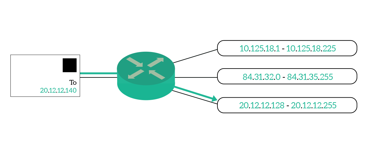
The router does not limit to route packets coming and going to connected subnets, it can also store information about remote subnets (not directly connected). This type of information is stored like that: To reach that subnet X, I must go through subnet Y. This way, all traffic intended to subnet X will be sent out of the interface in subnet Y. This process is done by all routers in the path until the packet reaches the destination. The information needed for the router to reach a specific subnet is called a route, and routes are all stored in the so-called routing table, with the list of all available destinations.
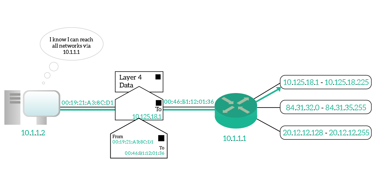
An interesting type of router is the default router. It is not about what it is, it is just a normal router, it is about what it does. A default router is the router through which all the devices in a subnet can reach everything else. The devices know that all the rest of the Internet will be reachable through that router, so all the traffic that is not for the local subnet will be sent to it. Source devices are intelligent enough to tell if a destination is in their local subnet or not. In case it’s not, they know that to reach it they have to send it to their default router. Because of that, they will create the IP packet for the correct destination but will put it in a data-link frame destined to the default router’s MAC address, so that it can get to it straight away. Then, the default router will check the destination IP against its routing table and will send it to the right next to the router in the path. The default router is also known as the default gateway, while routers in any given path are known as hops.
Now that we know how traffic is routed on the Internet, a single piece is missing from the picture: the IP packet has to be put inside a data-link frame to be sent to a destination MAC address. How can we know the destination MAC address, since it is not related to our subnet but rather to the hardware vendor of the destination device’s NIC? Let’s find that out in the next section.
ARP
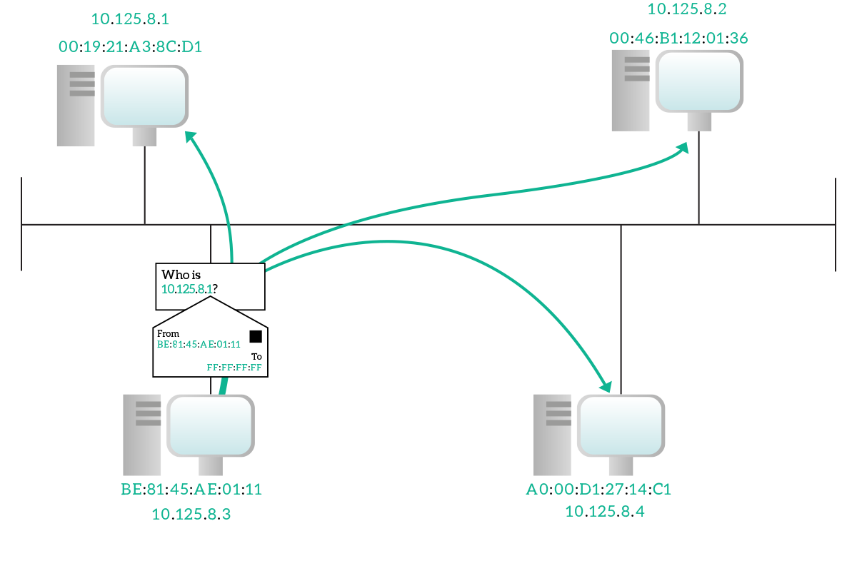
ARP stands for Address Resolution Protocol and it is a data-link layer protocol that creates a binding between MAC addresses and IP addresses. This protocol is used to obtain the MAC address of a device on your broadcast domain if you already know its IP address. This protocol is dramatically simple yet effective, the principle is this: we just ask. Yes, the device that knows the IP but not the MAC address of the destination uses ARP to ask “Who has this IP address? Could you tell me your MAC address please?”. This is known as ARP Request, and if it is successful a device in the same subnet will generate an ARP Reply, or ARP response, to inform the other device “Hey, it’s me!”.
Since we do not know the destination MAC address just yet, the ARP Request is sent inside a data-link broadcast frame. The key elements contained in this request are the IP address we are looking for and our own MAC address. We send our own MAC address to allow a device on the other hand to reply. You might think that sending our MAC address is not needed because the destination device already knows it from the data-link layer envelope, but this is not necessarily true. Not all devices learn MAC addresses from received frames, only switches do. More than that, the data-link envelope is discarded at the NIC-level on the destination device, so the process managing ARP won’t even read it. So, just to speed the process up, we send our MAC address in the request.
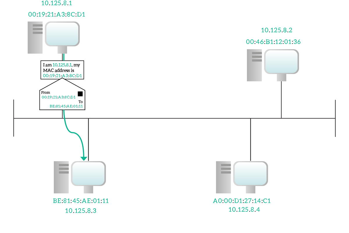
Since the destination device already knows our MAC address, it will reply directly to us in unicast at the data-link layer, writing its own MAC address inside the ARP Reply message. Once we have that, we can establish communication with it. Each time an ARP Request-Reply process ends successfully (that is, when the target device replies), we update a table stored in our device which maintains the binding between IP addresses and MAC addresses. That table is known as ARP table, or ARP cache and every record we add will be flushed out in some time (generally ten minutes) if we don’t receive any more traffic from it. If within these 1o minutes we receive a frame with that MAC address carrying a packet with that IP, the timer is reset back to 10 minutes.
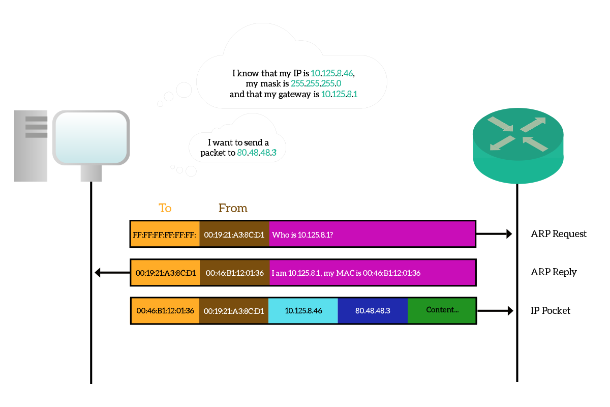
It may be worth spending some time to talk about the ARP process when we want to communicate with a remote host, a device which is not in our broadcast domain. To do that, we know we have to pass through our default gateway, but as soon as we powered on our device the ARP table will be empty, so we need to do some ARP requests to communicate. Our device is pretty smart, so when it realizes it is going to send a packet to a remote device, it will try to put that in a frame destined to its default router’s MAC address. If that MAC address is unknown, it will do an ARP request, asking who has the IP of the gateway, not who has the remote IP. The default gateway will reply with its MAC address, then the packet for the remote destination will be sent inside a frame destined to the default gateway. In case our source device is not so smart, or most probably has a wrong configuration, it might ask for the MAC address of the remote destination. The problem, in this case, is that the remote destination won’t hear that request because it is not in the same broadcast domain, but there is a feature implemented in routers that can help. It is the proxy ARP, which can be turned on or off according to our will. Its functionality is straightforward, the router listens to ARP requests and replies with its own MAC address if this request asks for its own IP or for an IP the router knows it can reach (even through other subnets). This should be avoided because the ARP table may get a lot of records (you won’t have just a record for your gateway, but for all the remote destination you try to contact), potentially experiencing some delay or unexpected behavior.
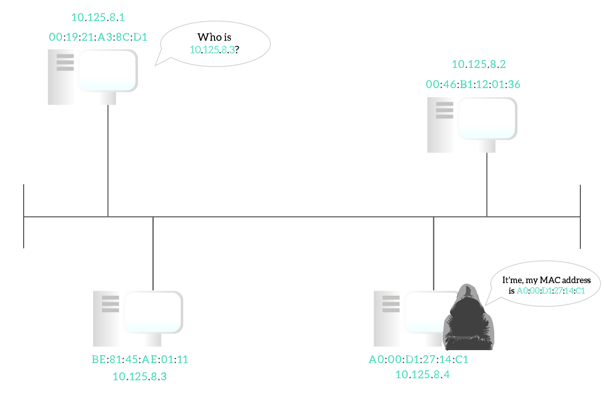
The Address Resolution Protocol is such a great invention because it allows the communication to be dynamically established, without having the need to manually configure the association between IP addresses and MAC addresses. However, this is the only purpose of ARP and without the proper precautions, it can lead to serious security exposure. When you do an ARP Request you do not know the destination MAC address just yet, so you will be ready to accept basically everything. More than that, you except just a single ARP reply, because the target device should be just one, so as soon as you receive it you will populate your ARP table. A hacker could send you a malicious ARP reply before the legitimate device has a chance to do it, so you will think you are talking with the correct destination device, while you are taking to the hacker instead. This attack is known as ARP spoofing because the hacker’s device impersonates another device by using its MAC address. Some old devices may also be vulnerable to Gratuitous ARP, or Unsolicited ARP: this is exactly what the name suggests, ARP responses sent without being requested. While the idea is not malicious, and it was conceived to allow devices to facilitate to maintain the ARP tables of one another without having some entries flushed out, this is a dramatically huge security issue because with normal ARP behavior the hacker must wait for you to make an ARP Request, and be faster than any other device. Instead, with Gratuitous ARP, it can just connect to the network, send a response, and override your ARP cache records. Fortunately, almost no modern device is configured to accept gratuitous ARP, and ARP spoofing can be denied with some configuration in a switch, that we will see later on in the CCNA Course.
With this article, we covered the functionalities of the Internet Protocol version 4, the one today in use to allow communication between remote devices at a world-wide level. With that knowledge, we are now ready to dive into the world of subnetting, learn about the different types of IP addresses (public and private), and start to understand an addressing plan.


2 Responses
You have explained each and everything in detail. I really like this article and it helps me in clearing the concepts of classless IPS as it is the main topic discussed in my computer class few days ago.
But I want to ask a question from you. Many classmates talk about hacking through IP address. They claim that Facebook password can be hacked if some one knows on which IP you are using the facebook. Same way when I join a forum, and connected it with my Facebook ID, it is well known fact that owner of the forum knows my IP address. So is it possible that he can hack my FB ID??? As he have my IP address and he also knew with what FB I joined his forum? Am I on risk in this case?
Thanks.
Dear Cheetan,
Thank you so much for your compliments. My goal here is to write articles that make networks clear to everyone, and with comment like this I know I am suceeding. Thank you!
Now, let me answer your question. Your home router has a public IP address, and all devices in your home will present themselves with that address when sending traffic to the Internet (if you are interestend in how they can present themselves with the IP of the router, read this article about NAT).
So, Facebook’s servers, your friend in a Skype call and pretty much anyone else in an Internet communication with you, will see your IP address: you are sending packets with that address as a source. This is completely normal, as it allows the other party to send you back the response traffic.
What can someone do if they manage to get your IP address? Pretty much nothing. However, it’s a starting point. They can send some traffic to your router and see if some services are exposed (which are not, in a home router). Then, if they find some exposed services, they can try to exploit them. Even if you had some exposed services, like if you are hosting a public web server, they will need to find a way to violate them. After that, they would also need to find a way to access your very own computer from which you are accessing Facebook. They would need to manipulate the certificate (Facebook is HTTPS), and only after that they would be able to get your credentials.
Unless CIA or NSA wants to get your Facebook credentials, nobody will have enough resources to do anything from your IP only. It is much easier to get infected by a keylogger when downloading files: the top places to get a virus are sites where you download copyrighted content illegaly (pirate movies, software, games etc.).
I hope this helps you! And teach your classmates some real networking!
Comments are closed.