In the previous article, we learned how STP works. Now it is time to put all our Spanning Tree Knowledge in practice, and start the configuration. In this article, we are going to do just that. Not only we will learn how to implement STP, but also how to fine-tune it to reflect our needs. We will then cover optional features like PortFast and BPDUGuard.
This article aims to teach you how to configure and troubleshoot Spanning Tree Protocol. The best way to do so is with a practice lab: download it for free from the link below. Then, open it with Packet Tracer.

Continue reading this article with the Packet Tracer file open, you will try what you learn in the demo environment. This way you will be mastering STP and its Cisco IOS commands in the blink of an eye.
STP Lab Introduction
The Topology
Spanning Tree focus exclusively on switches. Because of that, the topology for this lab contains almost only switches. Specifically, we have five switches with redundant connections and two clients to do some tests. Here’s an overview of what we are going to work with.
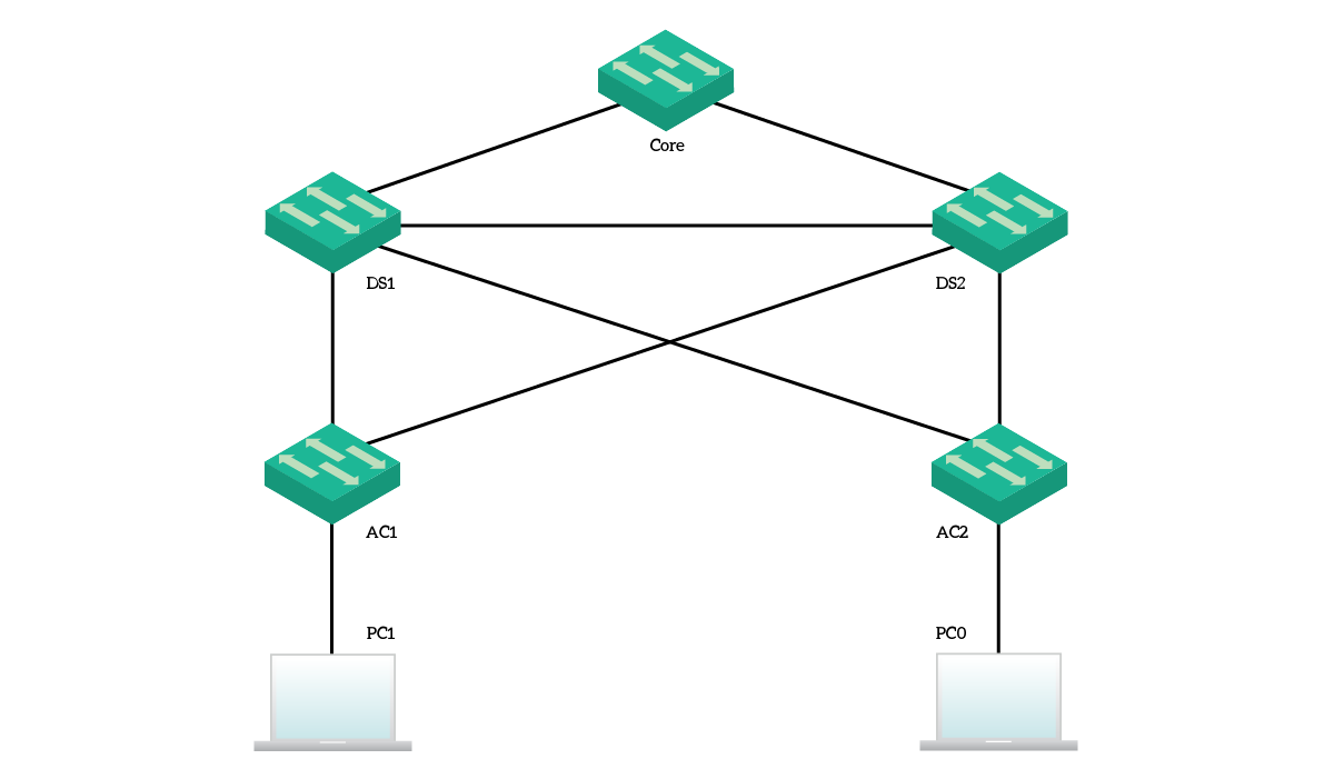
We have a core switch, two distribution switches, and two access switches. Then, we attached two clients, one per access switch. For this entire deployment, we are going to work with VLAN 10 and VLAN 1. However, since STP works within a subnet, we won’t have any default gateway. Instead, our final exercise will be to ping from a PC to the other and see where the packet goes. PC1 has the IP address of 192.168.1.10/24, while PC0 has 192.168.1.11/24.
The Requirements
Our overall requirement for this lab is to make the path selection process predictable within this switching domain. In other words, we want to configure the switches in such a way that we know which links are blocked by STP. To do that, we will need to tune priorities and port priorities to reflect our needs. Getting into the technical part:
- The network must run a fast STP version which creates a single instance per each VLAN
- We want the core switch to be the root
- The DS1 switch should be the secondary preferred root, in case the core fails – DS2 should be the third
- Access switches do not need a specific priority, because if both core and distribution are down access layer won’t work anyway
- We want the ports pointing toward the clients to be up as fast as possible, and still protect the switch from loops
By following this lab, you will see how simple it is to implement Spanning Tree and how you can protect your network in minutes. In the end, we will do some considerations about the most important things to do and do not do.
Configuring STP on Cisco Switches
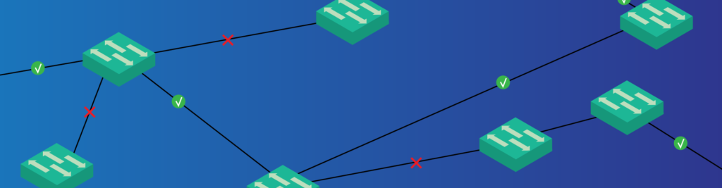
Before you start, take a moment to look at your packet tracer once it opens. You will see all links have amber dots. After a few seconds, many of them will turn green, while some others will stay amber. This is the way Packet Tracer tells us which ports Spanning Tree is blocking. If a port is green on one side, but amber on the other, it is blocked by the switch on the amber side.
Note that these light indicators refer to the VLAN 1 only. We might run multiple spanning tree instances, and they might have different roots and blocked ports.
Selecting the Spanning Tree Mode
Spanning Tree has many flavors. You can run plain STP, Cisco Per-VLAN Spanning Tree (PVST), Rapid STP, Rapid PVST, or Multiple Spanning Tree (MST). They all do the same things but in slightly different ways. For our lab, we are going to use Rapid PVST, a Cisco implementation. Its major benefit over the traditional version is the support for multiple VLANs. Since the default mode is non-rapid PVST, we need to change that on all the switches by typing the following command in configuration mode.
spanning-tree mode rapid-pvst
Rapid PVST, also known as PVST+, is still a Cisco proprietary implementation. However, it can run on normal 802.1Q trunks, instead of Cisco ISL trunks only. It supports the native VLAN, and it is fully compatible with the 802.1D STP standard.
Setting the root bridge
Now all switches agree on the Spanning Tree version to use. The next thing we want to do when dealing with Spanning Tree is the identification of the root bridge. It should be the switch at the center of the network, possibly the one with the uplinks to the Internet or to the Corporate network. In our lab, it is the “core” switch. We already know that we can influence the root bridge election by changing the priority of each switch.
Cisco offers two ways to do that. We can either set the priority manually or make the switch detect it on its own. If we go for the second option, the switch will look at the current root and use the priority right below the one of the current root. However, it will still write the exact priority in the configuration. To make the switch select the priority, we can use this command:
spanning-tree vlan 10 root primary
You can also use the secondary keyword. In this case, the switch won’t become the root. Instead, it will set its priority to be the next higher to the root. This way, in case the root fails, the switch will become the new root. We are not to use these commands in the lab, we are going to it manually.
Manual priority for the Root Bridge
For this lab, we are going to use manual priority and set the same one for VLAN 1 and VLAN 10. We can specify only values in an increment of 4096, because we can only change the leftmost bits of the priority fields. The others are reserved for the VLAN ID. A good practice is to set the root to be at priority 4096. This way, in case of emergency, you can set another switch to priority zero to be the new root. If you start with the root at priority zero, you won’t be able to elect a new root easily. The default value is 32768. So, on the core, we will use these commands:
spanning-tree vlan 1 priority 4096
spanning-tree vlan 10 priority 4096
This way, we are setting the priority for both VLAN 1 and 10. Remember, every time we modify the Spanning Tree topology, like changing priorities, spanning tree will need to converge.
Then, we can set the DS1 switch to have a priority of 8192 and the DS2 switch to have a priority of 12288. Always on both VLANs.
Tuning Port-Priority
Port priority is a determining factor when selecting the root port. However, the switch considers it only if the remote bridge ID received on two different interfaces is equal. This means that the two interfaces are connected to the same remote switch. You can use the Port Priority to prefer one over the other. A common example is if you have a GigabitEthernet interface and a FastEthernet interface.
In this lab, we tuned the cost of the FastEthernet 0/24 on DS2, but this is completely optional. That is, it won’t count for scoring purposes, it doesn’t add any value to the network, but you might want to try the command. In case you want to do it, use the commands below.
interface FastEthernet 0/24
  spanning-tree vlan 10 port-priority 240
This way, we are setting the port priority to the maximum allowed value for VLAN 10. Even there, Cisco allows us to go only in increments, this time by 16 each. Remember that the lowest the priority, the most preferred the port.
PortFast and BPDUGuard
Now the STP topology is converged, but we want to improve the performance on the edge ports. These ports are the one facing clients (or servers), in this case FastEthernet 0/23 of both access switches. We want to enable these ports as soon as something connects to them. This is the role of the portfast. However, in case someone creates a loop (like with an extra unmanaged switch), we still want to protect the port. Since we are not running STP anymore, we need to find a workaround. With BPDU Guard, you can immediately shut down the port as soon as it receives a BPDU. You know, just in case. We recommend using this feature alongside PortFast.
So, we need to enter the interface configuration and enter these commands (on both access switches). The first command enables portfast on the port, the second enables BPDUGuard.
interface FastEthernet0/23
 spanning-tree portfast
 spanning-tree bpduguard enable
In some other cases, we might want to turn these features on by default on all ports. We can do that by using two global configuration commands:
spanning-tree portfast defaultenables PortFast on all non-trunk portsspanning-tree portfast bpduguard defaultenables BPDUGuard on all PortFast ports
However, we are not using these commands in our lab. As a best practice, manually configure PortFast on the ports where you need it. Putting it on a wrong port may cause network outages.
See the packet going
Congratulations, you have completed this lab, but continue reading. Packet Tracer has an awesome feature, the Simulation Mode. With this feature, we can easily see where packets are going. If you need a refresh on this mode, we have a Packet Tracer introduction that will help you.
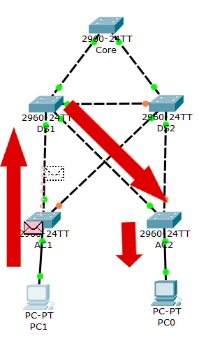
You can switch to this mode, turn on capture for ICMP traffic, and then run a ping from 192.168.1.10 to 192.168.1.11, or vice versa. You will see that switches will funnel traffic through DS1, and not to DS2. This is what we wanted to achieve, a predictable path between devices.
Troubleshoot and Verify STP
Until now, we went blind on the configuration. We just typed one configuration command after the other, and this is great to acquire knowledge on technology. But you shouldn’t do that on the production environment. Instead, you should have a clear understanding of what’s happening, and what could happen. In other words, you need to assess the current STP deployment of a potentially unknown network. To do that, you can use the Cisco commands to analyze the current Spanning Tree status.
In the real world, you need these commands to identify the root bridge and the blocked ports. But, most importantly, to predict what is going to happen if you change something (like changing the root).
A General Overview
To have a general overview, we can use show spanning-tree summary. This simple command gives a compact output with some generic information about Spanning Tree. It surely is a great starting point to check an STP configuration. Below, a sample output with its part highlighted for a better explanation.
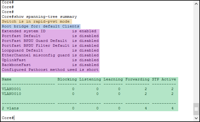
The first thing we see is the Spanning Tree mode running on the switch (Orange). We switched to Rapid Per-VLAN STP at the beginning of the article, and as a result, we see rapid-pvst here. Just after that, the switch tells which VLANs it is the root for (Blue). Instead of telling us the VLAN IDs, it tells the VLAN names. Remember that “default” is the name of VLAN 1.
Then, we have the list of the global-level STP options and their current status (Purple). Many of them are out of scope for the CCNA, but we can see that PortFast and BPDUGuard are here. However, they are both disabled: we are using interface-specific configuration, this tells the global-level status.
Finally, we have a recap of the ports and their status (Green). In this table, each row is a VLAN and lists how many ports are in each status. Since our network is already converged, and we are on the root bridge, STP is forwarding on all active ports.
Getting more details
The summary is a starting point, but we must go further than that. Interestingly, we can do it by removing the summary keyword from the command, resulting in show spanning-tree. This command, however, will create an extensive output for all the VLANs, which might be confusing. To make our life easier, we can trim the output to a single VLAN by appending the vlan keyword, followed by the VLAN ID. So, for this lab, we will use show spanning-tree vlan 10.
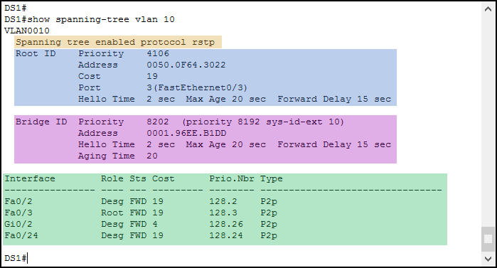
We can see we have a pretty good output for a single VLAN. As always, we start with the Spanning Tree mode running (Orange). Unlike the previous output, Rapid STP is simply known as RSTP here.
Just after that, we have the information about the Root Bridge (Blue). This paragraph describes the switch that the current switch believes to be the root. We can see its priority, its MAC address, the cost, and the port we use to reach it. You can use this information to do something smart. Lookup the MAC address in the ARP table, and get the IP address of the root. Then, you will be able to connect to it in SSH (if you configured it, not in this lab). If the local switch is the root, instead of the cost you will see “This Bridge is the root”.
The next paragraph is about the switch you are sitting at, the local switch (Purple). It tells the local priority and the local address. Then, we have a list of the ports that joined STP (Green).
Ports in “show spanning-tree”
Ports down at the physical layer (not connected to a device) are omitted here. For each port, you see these fields:
- Role tells you if the port is a root port or a designated one
- “Sts” stands for Status, and tells if the port is Blocking, Listening, Learning or Forwarding
- The Cost is entirely based on the port speed (GigabitEthernet is 4, FastEthernet is 19)
- “Prio.Nbr” is the composed priority of the port. The administrator can adjust only the first part (before the dot). We even did this on DS2 during the lab. The second number simply identifies the port, starting with FastEthernet0/1 which is port 1. You can’t change that, it will be used as an additional tiebreaker in case the priorities are equal
- The type is out of scope for the CCNA
With this in mind, you can easily assess an STP deployment. But we have more commands that might come in rescue.
Other STP Verification Commands
With the previous two commands, you can get all the information you need to troubleshoot STP. However, if you know some extra commands you can troubleshoot faster. With these other commands, you won’t get any new information. Instead, you will see only some pieces of information, trimmed for ease of use.
show spanning-tree interface, followed by the interface name (e.g.Fa0/1), tells you everything STP-related to that interface. You will see the state of the interface, for each VLAN. In fact, the same interface can be in different states for different VLANs.show spanning-tree inconsistentportstells you which ports are in an inconsistent state according to STP. This is beyond the scope of this article, as it tells you if some extra features like RootGuard detected an error.- Finally,
show spanning-tree detail. This tells you everything, in a descriptive way.
With these commands, you can boost your troubleshooting experience by getting to the output you need.
Final Considerations and STP Limitations
Spanning Tree is an awesome protocol, yet you shouldn’t use it as standalone. To benefit the most from it, you will need to use other features such as EtherChannels or Fist Hop Redundancy protocols. We are going to talk about them later in the CCNA Course. However, for now, we can still define the limitations of STP.
- STP is slow to converge (50 seconds), and it might struggle to handle more than 7 consecutive links. Because of that, try to use a Three-Tier infrastructure, which allows you to have many switches with short chains (the majority of switches are connected to the core).
- Cisco implements STP on a per-VLAN basis. This means that the same port may be accepting and forwarding traffic on some VLANs while blocking it for some others. Each VLAN you add automatically creates a new Spanning Tree instance, with its own timers and port states. Since each instance consumes resources, having many VLANs may slow down your switch, or even make it crash. To be sure, check the datasheet of your switch. To solve that, you can use Multiple Spanning Tree (MST), which is a CCNP topic. It basically groups multiple VLANs in a single instance, saving resources.
- STP has a simple goal: remove loops, and nothing more than that. If you have two independent links between the same two switches, STP will keep only one of them active. It will change that only if the first link fails
Keep in mind these points when designing your network. Having the right understanding of this technology allows you to create a great and scalable network.
Conclusion
In this article, we presented the configuration of STP on Cisco devices. If you were able to complete the lab, you now understand how to use Spanning Tree to manipulate a network topology. To do that, you will need to use some configuration commands. Here’s what you must remember, both for the exam and for the job.
- Use
spanning-tree modeto change the STP mode, such as Rapid PVST - Use
spanning-tree vlanpriority to set the priority of the switch for a given VLAN. This will influence the root selection - Turn on PortFast and BPDUGuard with
spanning-tree portfastandspanning-tree portfast bpduguard enable(in the interface configuration) - Troubleshoot STP with
show spanning-tree vlanandshow spanning-tree summary
Now that you have a complete understanding of what is going on in a Layer 2 topology, you can continue with the CCNA Course. As a next step, we will see what EtherChannels are and how we can use them to overcome some STP limits.

