Getting your CCNA is much easier if you try what you learn. Purchasing real gear may be expensive, especially if you are going to use them for the certification only. Fortunately, Cisco helps us with a network simulation software called Packet Tracer. This software is specifically designed for training, and it allows you to create a simulated Enterprise network in a few minutes. In this article, we will help you to get your Packet Tracer running for all the labs that you are going to find in the CCNA course.
The need for practice
The knowledge you get in the field is different than the one you get on the books. You can consider this statement as always true, but in networking, it is extremely true. In order to set up an Enterprise network, you should know pretty well all the configuration commands and the logic behind them. There are no shortcuts on knowing logic and concepts, but with the command, it’s a little bit different. Instead of memorizing all the commands word-by-word, if you understand how the Cisco device processes them you will be able to do the configuration anyway. You can get hints by the operating system, and you can rely on Google for quick searches. Moreover, real-world practice allows you to don’t blow up your network for a distraction. There are tons of items that you know about, but that you might forget about them when you are doing the configuration.
In our CCNA course you can find a lot of hints to avoid mistakes, but practice is the real deal. You have several options to apply what you learn:
- On the job training – if you are already working in Networking or ICT
- Simulation software, like Cisco Packet tracer
- Emulation software, like GNS3
Cisco developed Packet Tracer specifically for CCNA-level training, and this is why we chose it. While Packet Tracer cannot help you with CCNP labs, it is great to try out CCNA-level stuff. More than that, it is probably the simpler one to use and configure: download, install, done. Before getting into labs, as we will in the following articles, it’s time to get our Packet Tracer running.
Welcome to Cisco Packet Tracer
Obtain Packet Tracer
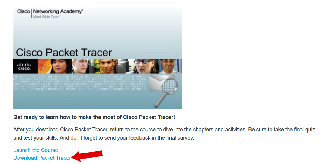
The first thing you have to do is download the Cisco Packet Tracer. You can find it for free on the Cisco Networking Academy website at this page. You just have to sign up for the Cisco Packet Tracer training campaign with name and email, then you will be redirected to the introduction course. From there, click on the “Download Packet Tracer” link on the main page. Select which version you want to download, according to your operating system (Windows? Linux? 64 or 32 bits?) and the download will start. Once you downloaded the software, just install it. The installation is a next-next process, no advanced stuff like driver setup, network services, or daemons is required. Once done, just launch the software so that we can take a look at its interface.
Extra tip: you can also get Packet Tracer for mobile devices, there is a version for Android and a version for Apple IOS. Cisco offers you QR codes pointing to the application (in Play Store and Apple Store).
Note: Packet Tracer will ask you to sign-in with your Netacad account (the one you just created when enrolling the course) every time you launch the software. You can avoid to login on every time by disconnecting your PC from the Internet the time you launch Packet Tracer. You can connect it back once it is opened.
Packet Tracer 101
For our CCNA course, we are using Cisco Packet Tracer 7. This version introduces a lot of cool features, like the Internet of Things (IoT) devices. From this version, when you launch the software you have to log in with a Cisco Netacad account in order to unlock full features. If you don’t have it, you can register a new one for free: this will be useful in case you want to follow some official training too. When you open packet tracer for the first time, you will be prompted to grant network access by Windows Firewall. Check both public and private networks and press OK, so that you can use Packet Tracer with your friends to work together on the same network (not needed if you plan to work on your PC only).
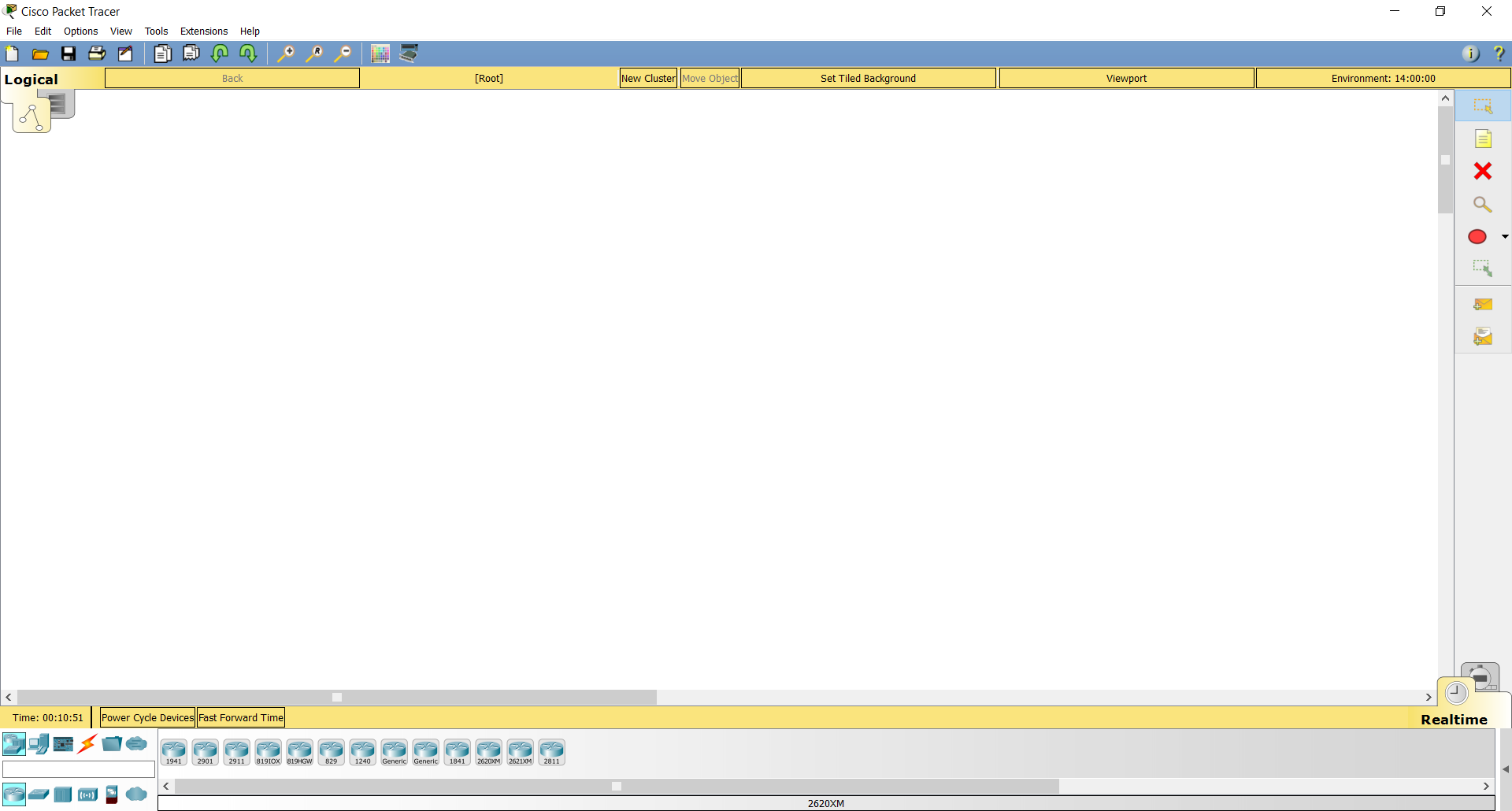
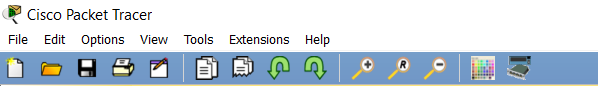
With Packet Tracer, you are able to actually draw a network, configure it and see how it works. You can even save it in a file and load it later. Let’s have a look at the interface appearing when you launch the software. As you can see, we have a big white window in the middle with several commands and menus around. At the very top, you have the list of commands you can find in any program: File, Edit, Options and so on. Then, on the blue top toolbar, you have some shortcuts to commands you can find in the menus above.
Topology toolbar
Just below the blue top toolbar, you can find a large yellow panel. This is the topology toolbar, containing useful information about your drawing. You will rely on these information if you want to format your file cleanly, with an image background and so on. However, for normal usage of Cisco Packet Tracer, you don’t need to worry about this bar.

The switch between Logical and Physical topology is the leftmost element of the bar. You can use it to switch between logical topology (icon with three dots) or physical topology (server icon).
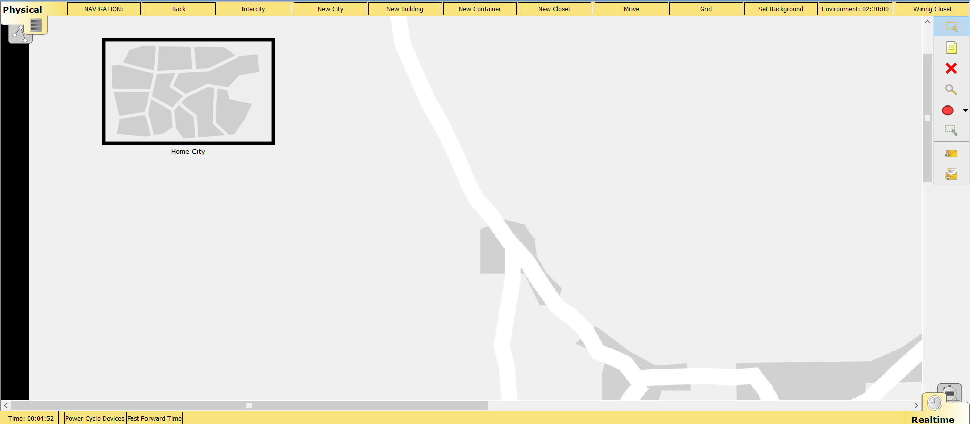
Besides that, we are going to use the logical topology almost all the time. This is because here we can see the logical interconnection between devices, and work with a clean white background. Just for you to know, in the physical topology we see the same devices in racks and wiring closets. Here’s a screenshot of a brand-new file with physical topology tab selected.
The Drawing menu
At the right of the drawing area we have the drawing menu, containing some tools to enrich your design. You can use this menu to place text notes in the drawing, add geometrical shapes and resize them. Inside this menu, you can also find some tools not related to drawing, but to packet inspection instead. For example, with the “Inspect” tool you can check the data travelling onto a cable. Packet inspection is a very cool feature of Cisco Packet Tracer, and we will see it later in this article.
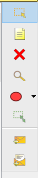
From top to bottom, the available command are these: Select, Place note, Delete, Inspect, Draw a polygon, Resize shape, Add simple PDU and Add Complex PDU.
Real-time and Simulation mode toolbar
Right below the drawing window, we find another yellow toolbar. This one is about the mode we want our devices to behave. We can switch between two modes, Real-time and simulation. In real-time mode, devices react immediately to your commands just like real-world devices. You can even fast-forward the time, for example to skip the bootup process. In simulation mode, instead, you have to press a button to move to the next instant. This allow you to inspect data travelling on cables, and it is very useful for debugging and learning purposes.

If you are in real-time mode, at the very left of this panel you can find the time elapsed since the creation of the current Packet Tracer file. Time increments, second-by-second, only if you keep the file open. Next to that, you have the option to power-cycle devices or fast-forward time. Clicking on “Power Cycle Devices” will cause all devices to reboot immediately.
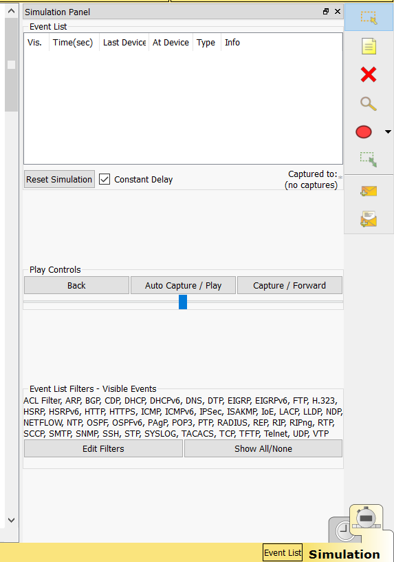
If you switch to simulation mode, you will find a new panel on the right. In this panel, you are able to see a list of packets sent along the network, and control they way Packet Tracer gathers this information. With the “Play Controls”, you define the way time passes. To do that, you have two options: manual forward or automatic forward. With manual forward, you have to press on the “Capture / Forward” button to see the next step a packet takes. Instead, with “Auto Capture / Play” this will be done automatically and slowly. Use the bar below that to adjust the speed. Below that, you can also set filters to specify which packets you want to see.
Device menu
We kept the most important menu for last: the device toolbar. At the very bottom of Packet Tracer’s interface, we have a large bar that we can use to insert devices into the picture. After adding a device from here, we will be able to control it from the drawing window. Before talking about that, let’s have a look at this toolbar.
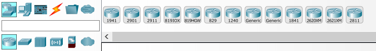
As from the screenshot, this toolbar is divided into two parts. On the left, we have two rows of icons: the top category is on top and the sub-category is on the bottom. If you hover any icon on these two rows you will see the description in the white rectangle that separates the row. Depending on the combination of category and sub-category, Packet Tracer will present you with different devices on the right part of the toolbar. There is no point in listing all the devices available in this article, it is a lot easier for you to explore the various tabs. However, Packet Tracer contains several models of switches, routers, end-devices, and – from version 7 – IoT devices.
To kick-start you, here’s the most important device categories we are going to work with. Above everything else, we are going to use network devices. Then, there are two other categories we have to use with them: end-devices and connections. In end-devices (the computer icon), you can find computers, smartphones and servers. Connections are instead represented by an orange bolt, and you use them to interconnect other devices.
Adding and connecting devices
How to add devices in the drawing window
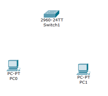
Now that we know how Packet Tracer works, it’s time to add some devices! Once you add a device to the drawing window you will be able to control it. So, using the device panel we already explained, select End Devices > End devices. Then, drag two “Generic PCs” into your drawing area. After that, move to Network Devices > Switches and drag the switch named 2960 (2960-24TT) into the picture. For simplicity, we put them in a triangle shape.
How to connect devices together
Now that we added the devices, we need to connect them together. To do that, select the Connections > Connections category. Now we have several possibilities, among them you can make Packet Tracer decide which cable suits best every condition. However, for today we are going to use a simple Copper straight-through cable (the black solid line). You know from the previous articles that a device can have multiple NICs, so how do we select the one to plug the cable into? It is extremely simple. Just select the cable, then click on a device you want to connect: a menu with all the available interfaces will open.
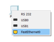
For this example, we will connect PC0 FastEthernet 0 to Switch FastEthernet 0/1 and PC1 Fast Ethernet 0 to Switch FastEthernet0/2. As soon as you connect the cables, you will see some colored dots on their ends, as in picture below.
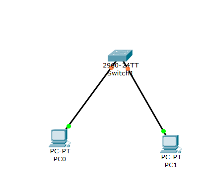
Data can travel over a cable only if the two dots on it are green. However, when you connect the cables you will see the switch side turning orange. This is because the switch is doing some checks before turning on the interface, so you just have to wait (or fast-forward the time). The dot indicating the port-status refers to the interface status of the closest device. It can be of three different colors.
- Green – the port is working at OSI layer 1 and 2
- Orange – the port is powered on, but software is blocking it
- Red – the port is shut down
Once your ports become green, you are ready to see how we configure devices in Cisco Packet Tracer.
Configuring devices in Cisco Packet Tracer
Configuring a Network Device
In Packet Tracer, you are going to work with a huge variety of devices. Therefore, you are going to face different ways on configuring devices, depending on the device itself. Two major device categories exist: network devices and end-devices, each with its own configuration.
You are going to configure network devices by using the CLI (Command-Line Interface), where you interact with the device using text only. To reach the CLI of a network device, just click on it with the select tool. A new window will pop-up, and from its tabs you just have to select CLI. This way, you will gain console access to the device.
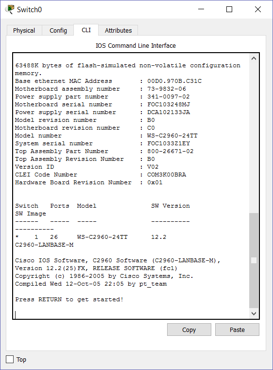
In this tutorial, we are not going to configure any network device. The only switch we added will work out-of-the-box, no configuration needed. Instead, read on to see how we will configure end devices.
Configuring End Devices
Configuring end devices is relatively simple, as you can do it completely from the Graphical Interface of Cisco Packet Tracer. The mechanism is always the same, just click on the device you want to configure and a new window will pop-up. From that window, navigate to the config tab. In there, we need to configure the FastEthernet 0 interface, so click on that from the menu on the left (if you don’t see it, click on INTERFACE from that menu to see the interfaces).
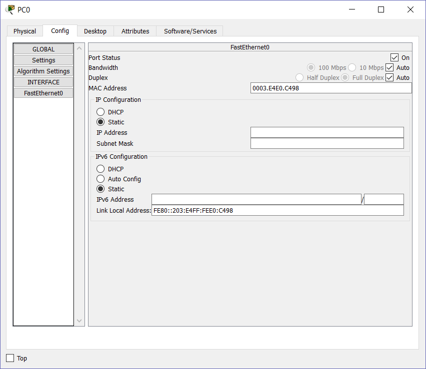
In this window, select “Static” in the “IP Configuration” box. Then, configure the PC on the left with an IP address of 192.168.1.1 and a subnet mask of 255.255.255.0. After that, configure the other PC with an IP address of 192.168.1.2 and the same subnet mask as the other one. For now, you don’t need to specify anything else: you can just close those windows, Packet Tracer will maintain the changes you made.
Packet Tracer Simulation mode
Getting ready for the capture
In networking, we call capture the content of a packet that we catch for debugging purposes. In other words, a packet is flowing onto a cable and we are able somehow to check its content when it’s in the cable. Packet tracer allows us to do so in the simulation mode, but we must create some traffic to capture. The first thing we want to do is to switch to Simulation mode. Now, nothing can happen unless we manually forward the time. Anyway, before that we need to configure capture filters to tell Packet Tracer which type of packets we want to see.
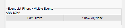
By default, Packet Tracer will listen to everything. To change that, click on “Show All/None” to remove all active filters. Then, click on “Edit filters” to manually add ARP and ICMP, that you can find under the IPv4 tab. Now, we are ready to generate the traffic to capture.
Generating traffic
For this example, we are going to generate some traffic going from a PC to the other. The traffic we are going to create is ICMP, and we are going to do so with a ping command. Basically, with ping, a PC asks the other “Are you there?” and the other one responds.
Select the PC on the right, then go to the Desktop tab and click on Command Prompt.
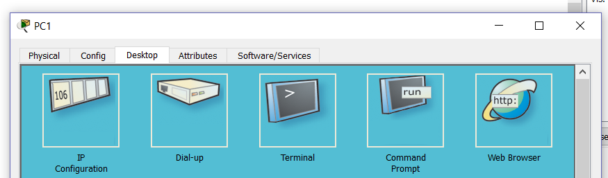
Once the prompt opens, ping the IP address of the other PC. In this case, we are going to do that with the command ping 192.168.1.1.
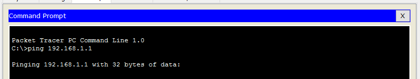
Now, nothing will happen because Packet Tracer is waiting for us to forward time. Meanwhile, if you check the drawing area, you will see that two packets are buffered on your PC waiting to go onto the cable.
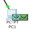
Each protocol is indicated with a color, so two packets of the same protocol will always have the same color. In this picture, two packets of two colors exist: one is the ICMP and one is the ARP. You can see that they are waiting to be sent because of the loading icon of moving bars on the envelope. Press Capture/Forward in the simulation menu to send the first packet onto the cable.
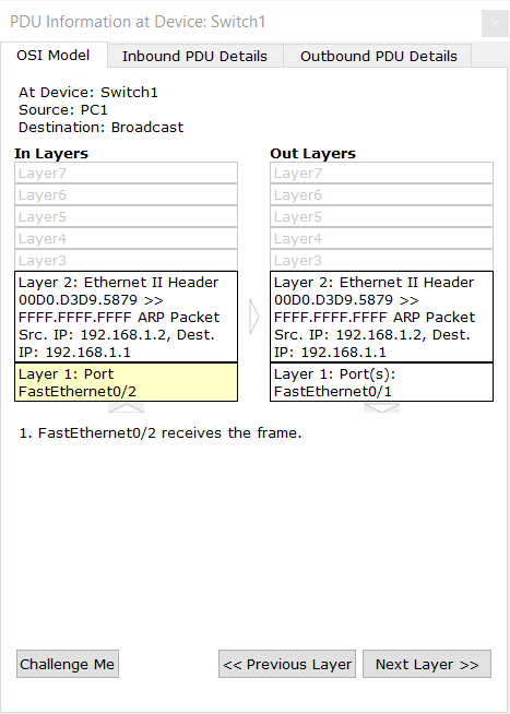
Checking the content of packets
If you think this is good, Packet Tracer has even more to offer. If you click on any envelope, you will be able to see all its details, including the headers at any OSI layer. Here’s an example of the ARP packet.
Now, it’s time for you to play with this feature and see how the ICMP requests go on. Remember to check the prompt of your PC once finished to see the records of the replies.
Conclusion
After this article, you should now have Packet Tracer up and running on your PC. More than that, you know how to use it. This is going to be extremely important as we continue with the CCNA course, as you will use Packet Tracer to try everything you learn, with the help of our guided labs.

