
The transport layer is the one bridging applications onto the network, and Transmission Control Protocol (TCP) is the protocol that can do it in a reliable manner. We already explained the differences between UDP and TCP in the previous article, and now it is time to understand how we can improve TCP performance to satisfy the requirements of modern applications and use the underlying network in the best way possible. In doing so, we will learn about the principles on a host that regulate the TCP connection, such as states and windowing operations: welcome to the article about advanced TCP!
TCP States
The theory of TCP states
To run TCP, any device must put in place some principles: it must know that it has to re-transmit when a ACK is not received, it must know that it has to send acknowledgments for the data it receives and so on. All of these rules can be defined in a state diagram, or flow chart. At any given time, the device must be in one of the states in the diagram, but in only one of them. Based on the state the device is in, it can do some operations instead of others, and can transition to other specific states. At a first glance, the diagram may seem very complex, but it’s not. Let’s have a look at it and then explain what does it mean.
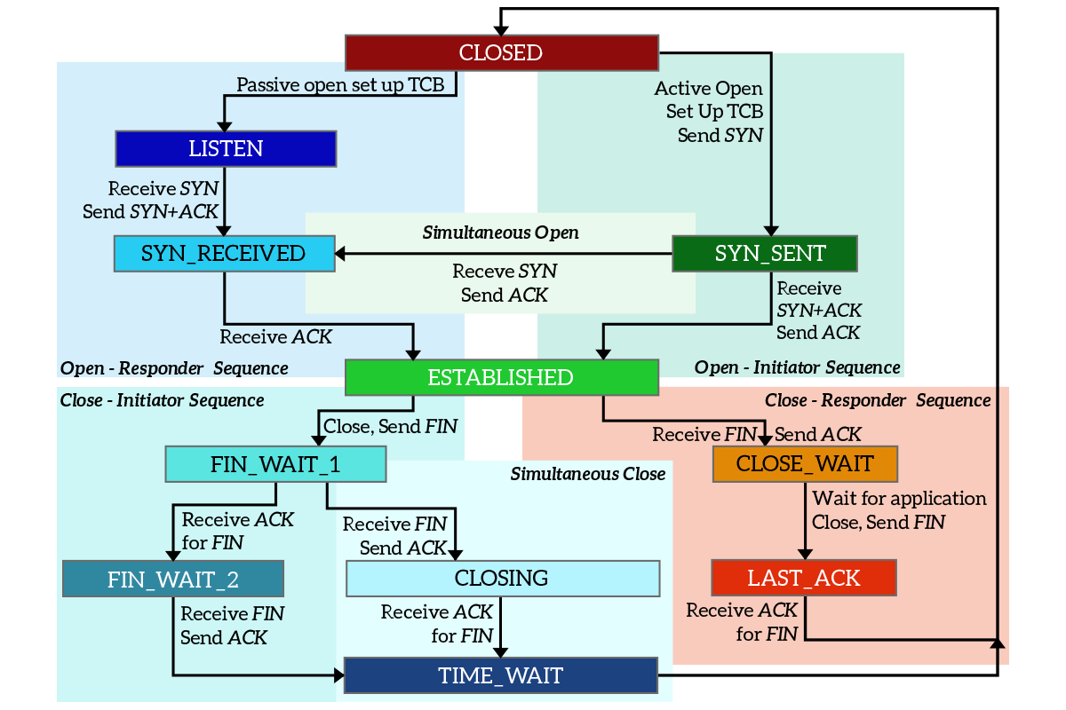
Let’s break down this complex topic. As you can see, there are 11 different states in the picture, and there is no true starting point. This means that any other state can be reached from at least another state (there is an arrow pointing toward it). Each state is represented by a rectangle, while the arrows pointing out of it indicate the states that a device can move to from the current state. The text on the arrow indicates what must happen for that state transition to succeed. Finally, all the states are grouped into different colored areas: this is just to group states that together aim at the same purpose.
Note: you can find states written in different ways in different books, using underscores, dashes or even nothing to join words.
Even if there is no true starting point, we can think that it is the CLOSED state: in this state, the connection cannot even be opened. This is because any connection starts with no connection; think about it, originally there is no connection, but then with the three-way handshake it is negotiated. A device willing to open a connection can move from the CLOSED state to two other states, depending on its role. Let’s think about the server-side (known as Responder here) first. The server does not initiate connections toward the client, but instead, it waits for clients to make requests. This means that the server must be ready to accept requests, and to do it moves from CLOSED to LISTEN state as soon as the application starts. This state indicates that the server is ready to receive connection, and will wait for SYN from any client.
The device deciding to actively start a connection is known as Initiator in the diagram, and it generally is the client. It moves from CLOSED state to SYN_SENT state just by sending the SYN to the server. Once the responder receives the SYN while being in the LISTEN state, it replies with SYN+ACK and immediately move to the SYN_RECEIVED state. Once the initiator receives that message, it transitions to the ESTABLISHED state by sending an ACK to the responder, which will transition to the ESTABLISHED state too as soon as it receives the ACK. This means that the connection is established, and data can be exchanged.
Note: when a connection is initiated, the Transmission Control Block (TCB) is defined. It is a set of information and variables to be stored in the memory of the device for the entire time of the connection. This includes the source and destination ports.
Once the data exchange is completed, some of the two devices will want to close the connection. Even in this case, we have a device initiating the closure (Initiator) and a responder to it, but this does not necessarily mean one is the client and the other the server. The initiator is just the device actively starting the closure process, while the responder is the one responding to the initiator (passive closure). The initiator will send a FIN, moving from ESTABLISHED to FIN_WAIT_1 state, and the responder will move to CLOSE_WAIT state as soon as it receives that FIN, sending an ACK in response. When the initiator receives that ACK, it will just move to the FIN_WAIT_2 state and will sit there doing nothing. The responder is still in the CLOSE_WAIT state, as it is waiting for the application to finish all its stuff and close. As soon as the application finishes, the device will send a FIN to the initiator to tell that it wants to close the connection too, and by doing so it transitions to the LAST_ACK state. Once the initiator receives the FIN from the responder, it will send an ACK and move to the TIME_WAIT state. As soon as the responder receives the ACK, it will move back to the CLOSED state. After a timer of two milliseconds, the initiator will move to the CLOSED state too. The connection has now ended according to both parties involved.
Transmission Control Protocol’s states applied
It might seem a little bit complex, but as soon as you see it applied to a connection it will start to make sense. Here’s a typical TCP connection with the states each device goes through.
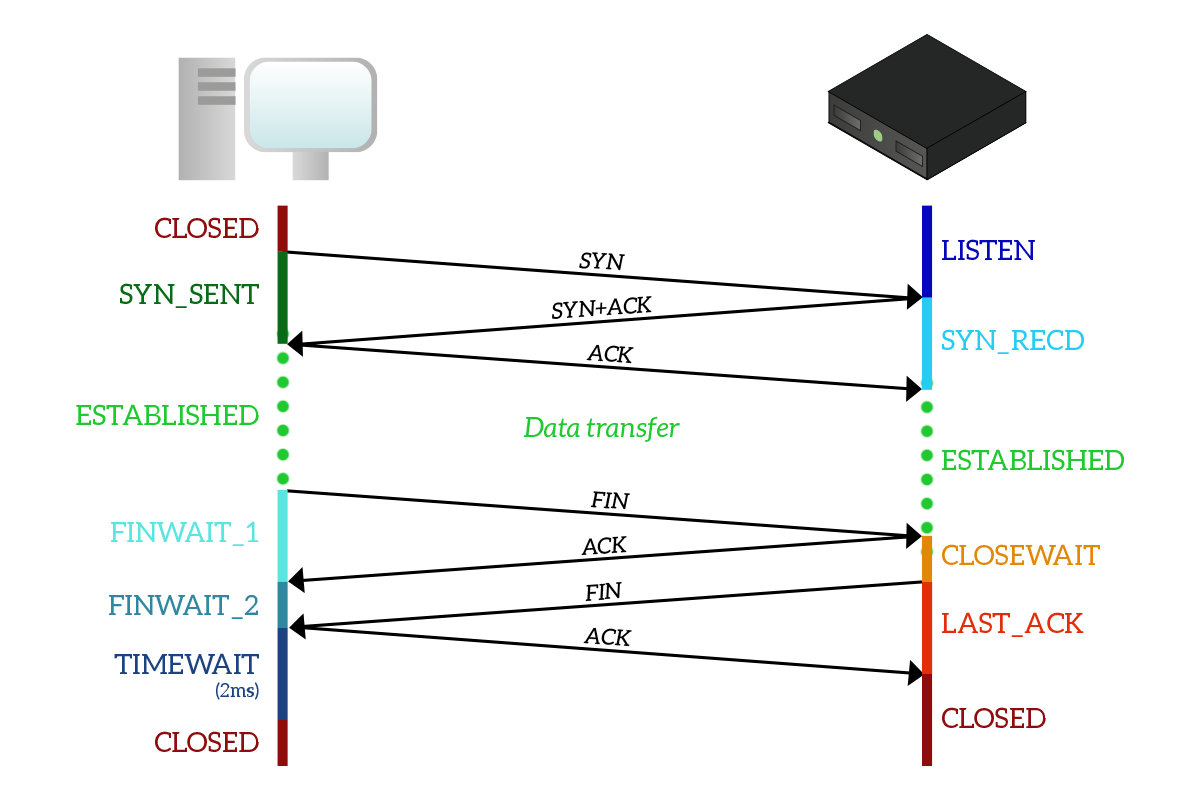
Before we start with the explanation, remember that states are significant to the connection onto the device: they are not states of the connection itself, so a device can be in a state and the other one in a different state. As you can see, the client start with the CLOSED state but the server is already in the LISTEN state because the application on the server which has to listen to requests and craft responses has already started. The client sends a SYN and moves to the SYN_SENT state. Once the server receives that SYN it will move to the SYN_RECEIVED state by sending SYN+ACK back to the client, which will move to the ESTABLISHED state and send an ACK in response. As soon as this ACK is received, the server moves to ESTABLISHED state too.
Note: the server transitions from LISTEN to SYN_RECEIVED state for each connection it receives, as it can accept multiple connections from different clients at the same time. This means that every time it receives a SYN it will create a dedicated instance of the state diagram for that connection, that will be destroyed as that connection finishes. This way, there will always be an instance in the LISTEN state ready to accept new connections from new clients.
Once the data exchange has been completed, it is the client in this example that wants to terminate the connection. It does that by sending a FIN and transitioning to FIN_WAIT_1 state. When the server receives that FIN, it will reply with an ACK and move to the CLOSE_WAIT state. When this ACK is received by the client, it will move to the FIN_WAIT_2 state, waiting for the server to close. Once the server finish what it was doing, it sends a FIN too, moving to the LAST_ACK state. When that FIN is received, the client sends an ACK and moves to the TIME_WAIT state and, after two milliseconds, to the CLOSED state. When that ACK is received, the server moves to the CLOSED state too. The connection has ended.
Simultaneous Closure
There is an interesting case is worth spending some time on: the simultaneous closure of a TCP connection. In this case, there is no active initiator and passive responder for the closure, but instead, both devices are actively trying to close the connection at the same time.
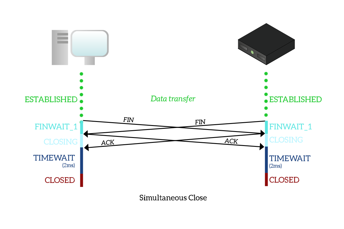
As you can see from the picture, this closure process is perfectly symmetrical. The client sends a FIN to the server to close the connection and moves to the FIN_WAIT_1 state. At the same time, the server sends a FIN to the client with the same intention, moving to the FIN_WAIT_1 state too. The client receives a FIN, so it moves to the CLOSING state sending an ACK. The same goes to the server, which receives a FIN too and move to the CLOSING state by sending an ACK. When any of the two devices receives the ACK, it moves to the TIME_WAIT state and, after the timeout, to the CLOSED state. Basically, with a simultaneous closure, a FIN flag is received while still being in the FIN_WAIT_1 state.
There is also a simultaneous connection opening that works the same way (a SYN is received while in the SYN_SENT state), but it is very uncommon to find in real life as the client-server model is the dominant one, and in this type of architecture it is always a device deciding to connect to the other, not both of them.
Reset of a TCP connection
We all know that a device can use the RST flag to move to the CLOSED state any time it decides to do so. This is highlighted in the following picture, which shows the two possible cases that can happen when a RST is issued.
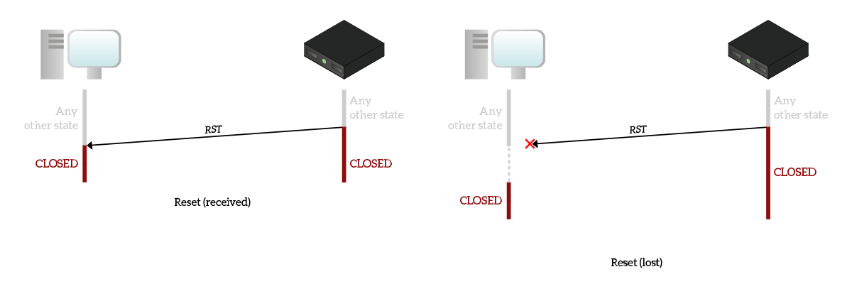
In the first picture, the reset is sent and received. As you can see, it can truly be sent while being in any other state and as soon as the device send it, it closes the connection immediately. This means that it is not willing to listen nor accept anything else from that connection, so when the other device receives the RST it won’t have any choice but to close the connection immediately.
The other case, explained in the second picture, is the case when the RST is lost. As this is the very last segment sent, no re-transmission will be put in place for it. The device sending it will close the connection immediately, and won’t process any more packets for that connection. This way, the other device that has not received the RST will still try to send data but, since it won’t receive any acknowledgment, it will consider the connection to be closed after a timeout.
TCP Windowing
In the TCP segment’s header, we can find a 16-bit long field called Window Size. It identifies the receiver window, which is the ingress buffer for that connection on the device sending that segment. Let’s state it in plain English. Window Size is the number of bytes that the device sending the segment can store waiting for the application to process them. This is applied to data received only. By sending that value in a segment, the device is saying “Hey you, you can send me X bytes and I guarantee I will store them in my temporary memory so that the application will process them eventually”, where X is the Window Size value.
Window Size is sent in every segment, but it is the other device that has to keep track of it: the Window Size indicates the entire size of the receiver window, and do not specify how much is already used. To keep track of the part of memory already in use on the other device, a device must compare the data sent with the data acknowledged. Each segment sent is assumed to occupy space in the receiver window of the other device, and each segment acknowledged is assumed to be removed from the receiver window, emptying some space. Remember that all of these operations are not performed considering the number of segments, but instead the number of bytes in every segment. Let’s have a look at the following picture to clarify that.
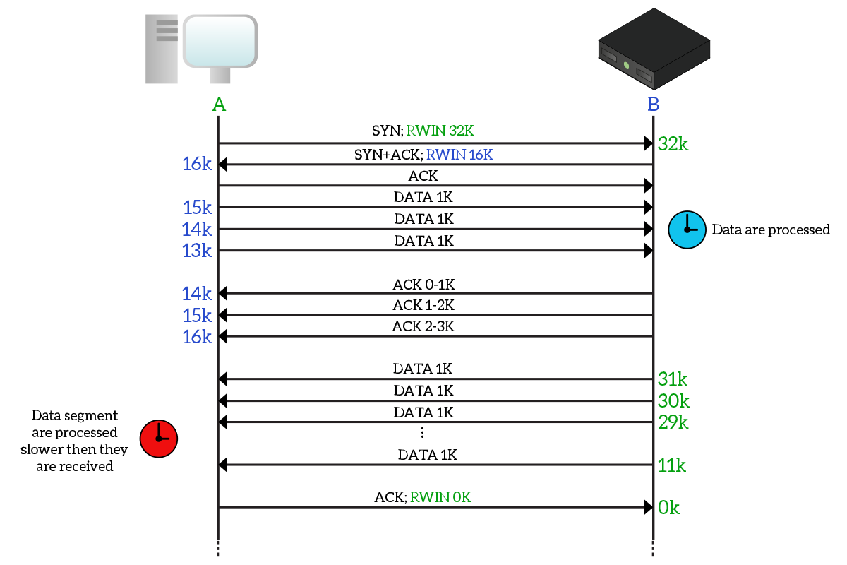
To simplify this even more, we named the client “A” and the server “B”. When negotiating the connection with the three-way handshake, the two devices tell one another their window size: A has a receiver window (RWIN, or RWND) of 32KB, while B has a receiver window of 16KB. Each device will remember the receiver window of the other device and it will consider it to be the space available on other’s device buffer. However, since no information is exchanged about “how full the buffer is”, the device must keep track of it. The good news is that the only thing filling up the buffer of the other device is the data we send to it: we know the total capacity of the buffer and we know it starts empty, but we also know how much data we are sending and how many data is acknowledged. This example is purposefully simple: the client sends 1K of data every time and therefore decrements the available space on the server’s buffer of 1K. It does this three times, meanwhile, the server starts to process data and send acknowledgments back. Each acknowledgment received, the client checks how many bytes are acknowledged and increases the available space of that number of bytes.
Later on, it is the server that wants to send data to the client. However, it has a huge load of data to transmit: it sends 1k at a time, 20 times (many are omitted in the picture), reducing the available space from 32k to 11k. The client might have a tough time in processing data, and in case it starts to get overwhelmed (as in this case), it can tell the other device to stop transmitting by sending a Window Size of zero.
Note: Window size is sent in every segment, and in every segment, it defines the total space available in the buffer of the device sending it, so unless that value is different from the one originally received during the three-way handshake (or than the last one, if it changed multiple times during the connection), the device won’t consider it.
This is because a device will transmit as many bytes as it can, but the number of bytes left unacknowledged cannot exceed the Window Size. Receiver window size has been specifically designed to avoid overwhelming devices, as if their buffer is full any segment received that cannot fit on the buffer will be dropped. With modern devices, it is rarely stressed. It can be used in conjunction with the congestion window to handle network congestion, as we will explain later on in this article.
Selective Acknowledgement
Selective Acknowledgement, known also as Selective ACK or simply SACK (RFC 2018), is another improvement to TCP performance that allow a device to acknowledge segments individually. In the traditional implementation of TCP, when a segment is lost, it has to be retransmitted, and all segments after the lost one have to be retransmitted too, even if they were received correctly. This is because of the nature of the acknowledgment number, which tells the other device which byte is expected next. With that logic, we can acknowledge a contiguous stream of bytes, but we are unable to put gaps in it (e.g. “Okay, I got 0-8 and then 10-20, but not from 8 to 10”). SACK does just that, it allows a device to individually acknowledge segments, so that only the lost ones are retransmitted, with an overall improvement of throughput. In the following picture, we compare traditional acknowledgment mechanism to SACK.
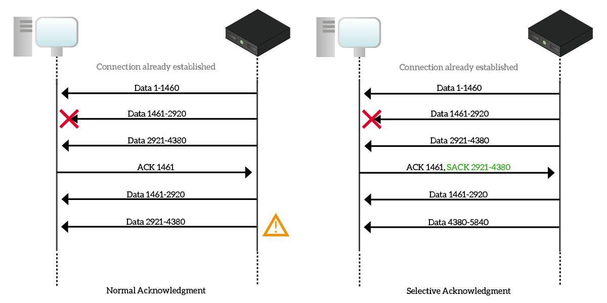
In the first case, with the traditional ACK system, the server sends bytes 1-1460 to the client, then 1461-2920 in another segment and 2921-4380 in a third segment. However, the second segment containing bytes 1461-2920 is lost due to a temporary problem over the network, so the client Acknowledge the first segment (sending an Acknowledgement number of 1461), but drops the third because if the acknowledgment number were 4381 there would have been no ways to tell about the segment missing in the middle. So, with an acknowledgment number of 1461, the server re-transmit bytes 1461-2920 (the lost segment), but also 2921-4380, which was delivered to the client successfully. This way, we are sending twice a valid segment, wasting bandwidth and time.
To solve that, SACK implements two different TCP header options. The first one is called Sack-Permitted Option and has an identifier (kind) set to 4. This option is used during the three-way handshake to verify that both TCP partners support the SACK mechanism. In case this first phase is successful, the Sack Option (kind set to 5) is used. Explaining the format of this option is out of scope, but just know that it is a space in the TCP header that is used to tell the other device which segments are acknowledged with SACK. If you want to go deeper on this feature, check out the RFC. Basically, when a segment is lost and other segments after that are received, everything before the lost segment is acknowledged the traditional way, and every segment after the lost one is acknowledged with the SACK mechanism, using appropriate fields in the TCP “Sack Option” header expansion. As in the picture, since the only segment lost is 1461-2920, the client acknowledge with traditional ACK bytes up to 1461, while with SACK it acknowledges bytes 2920-4380.
Header Compression
Header compression is a cool TCP feature that allows bandwidth enhancement on low-speed links, such as satellite connections. This feature is extremely simple, yet different from any other, because it is not implemented on TCP hosts. All the other features we covered were enhancement put in place by the two TCP partners, the devices hosting applications and talking to one another, while in this case they are not involved at all. Instead, this feature is implemented on the routers (network devices) in the path.
Imagine a router that has to process IP packets containing TCP segments, if you are doing some heavy use of a connection (such as downloading a file from a server), the router will see a lot of packets with the same source and destination IPs, all of them containing the same source and destination ports in the segment’s header. All of this has to be sent to the next router in the path so that it can continue to route packets properly. However, headers occupy bandwidth that lower performance even in a sensible manner on low-speed link. Since all these headers remain the same for the whole connection, couldn’t we send them just once? With header compression, we can.
A router implementing header compression takes IP and TCP addresses in the header, plus other fields that will not change during the connection, and run an algorithm on them to extrapolate a unique identifier (hash ID) which is much more smaller. In most cases, we start from 40-bytes long headers and we compress them to a 4-byte identifier. Obviously, all the router’s receiving a compressed header must know its expanded value to send the packet/segment to the right destination. In the end, a router will de-compress the header and send the normal one to the destination device (or to another router not supporting header compression).
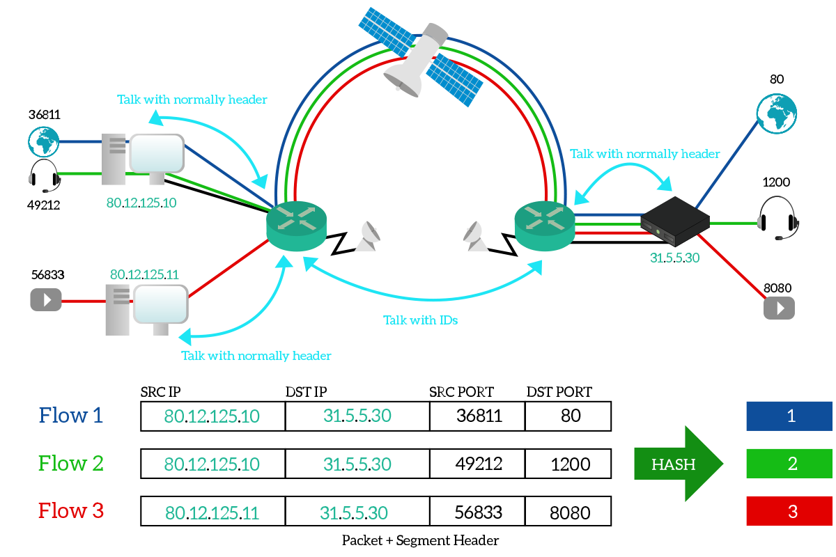
As you can see from the picture, the two routers talk over the satellite connection using hash IDs, with each hash that uniquely identifies a data flow. In this picture, we have unidirectional flows only, but in reality, there would have been a hash ID for response traffic too.
Handling network congestions
Fast retransmit
Fast retransmit is a very simple feature to implement aggressive re-transmission of data. In a normal TCP implementation, we should wait for ACKs to decide what we have to retransmit. With fast retransmit enabled if an ACK is not received within a specific timeout, the segment not yet acknowledged is automatically re-sent, to save time. This can unnecessarily saturate high-latency low-bandwidth networks, as information is not truly lost but it simply takes time to arrive on the other side.
TCP congestion control
Building networks is becoming cheaper and cheaper, we can achieve throughputs that we believed impossible even 10 years ago. However, as the speed of the network increases, the requirements of modern applications increase too. We use daily bandwidth-consuming applications, such as VoIP, video streaming, or massive online gaming. Therefore, leveraging 100% of the network speed is a must, but if we try to send many more data than the network can handle, we will cause a drop in performance. We need to find a way to use as much bandwidth as possible, without flooding the network with traffic and overwhelming it. We need some tools to control the congestion, and TCP has those tools.
The two TCP partners are only two hosts at the very edge of the network, they cannot know how the entire network works and, therefore, they cannot know the effective throughput they have between each other. Instead, they must find a way to determine it. To do that, we use the congestion window (CWND). That is the number of bytes that can be sent before we must stop and wait for an acknowledgement. The congestion window is local to the device and never shared on the connection, unlike the receiver window which is sent in every segment. At any given time, a device can send at most the number of bytes specified by the minimum between the receiver window and congestion window, as in the following formula.
transmittable bytes = min(cwnd, rwnd)
This means that if the congestion window is smaller than the receiver window, the device can transmit up to the number of bytes defined in the congestion window before waiting for acknowledgments. Instead, if the receiver window is smaller than the congestion window, the device can transmit up to the number of bytes defined in the receiver window before waiting for an acknowledgment.
The congestion window varies dynamically based on network congestion. Every time a segment unacknowledged, it is assumed to be due to network congestion. The way the congestion window evolves over time is defined into an algorithm, which depends on the implementation. We will present now one of the most common ones. The algorithm follows these rules:
- Congestion window starts with the size of one segment (around 1KB)
- A congestion window threshold (ssthresh) is defined
- If an acknowledgment is received, and the current congestion window size is lower than ssthresh, the congestion window doubles
- If an acknowledgment is received, but the congestion window is greater or equal than sshthresh, the congestion window increases by its initial value (e.g. 1KB)
- If a segment is not acknowledged so that retransmission is triggered, congestion window is cut in half and ssthresh is put at this value
- The congestion window cannot be greater than receiver window
To simplify the explanation, we crafted a sample segment exchange and applied the congestion control mechanism to it. As you can see from the picture below, each device keeps track of its own congestion window (CWND, green) and of the receiver window (RWND) of the partner. On the left, we numbered the segment exchange (row-column) to refer to the single line later.
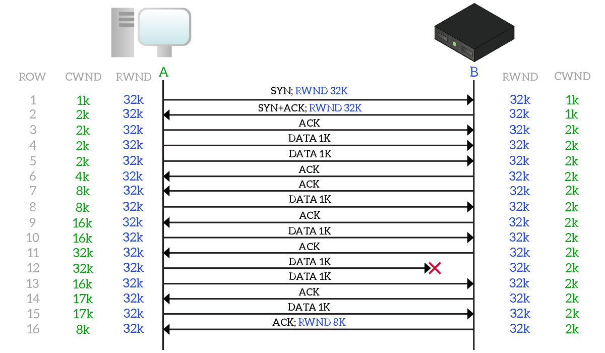
When negotiating the connection, the two devices exchange their receiver window (they both have 32KB in this case). They also both starts with 1KB of the congestion window, but since the client will be the only sending data in that example, it will be the only one significantly using this value. In line 2, the client receives an ACK and double its CWND (now it is 2k), and the server does the same when it receives an ACK on line 3. Then, the client sends two segments of 1k of data each, that they are later acknowledged on lines 6 and 7, where the congestion window on the client is doubled (4k, then 8k). Then, we have another exchange, where the client sends 1k of data which is immediately acknowledged, effectively doubling the congestion window again (now 16k on line 9). This is repeated in line 10-11, where the CWND reaches 32k. At this point, the congestion window cannot grow anymore unless the receiver window grows too. Instead, in line 12 a segment is lost, and, after a timeout (not shown in the picture), the congestion window and ssthresh are set to 16k. Then, on line 13-14 1k of data is sent and acknowledged, but this time the congestion window do not double, has it is already equal to ssthresh. Instead, it increases by its initial value (1k). In the final line 16, the server reduces its receiver window to 8k, so the congestion window on the client is set to 8k too.
This is a good example, but let’s have another one. Instead of representing the segment exchange, we will present a chart showing the evolution of the congestion window over the time.
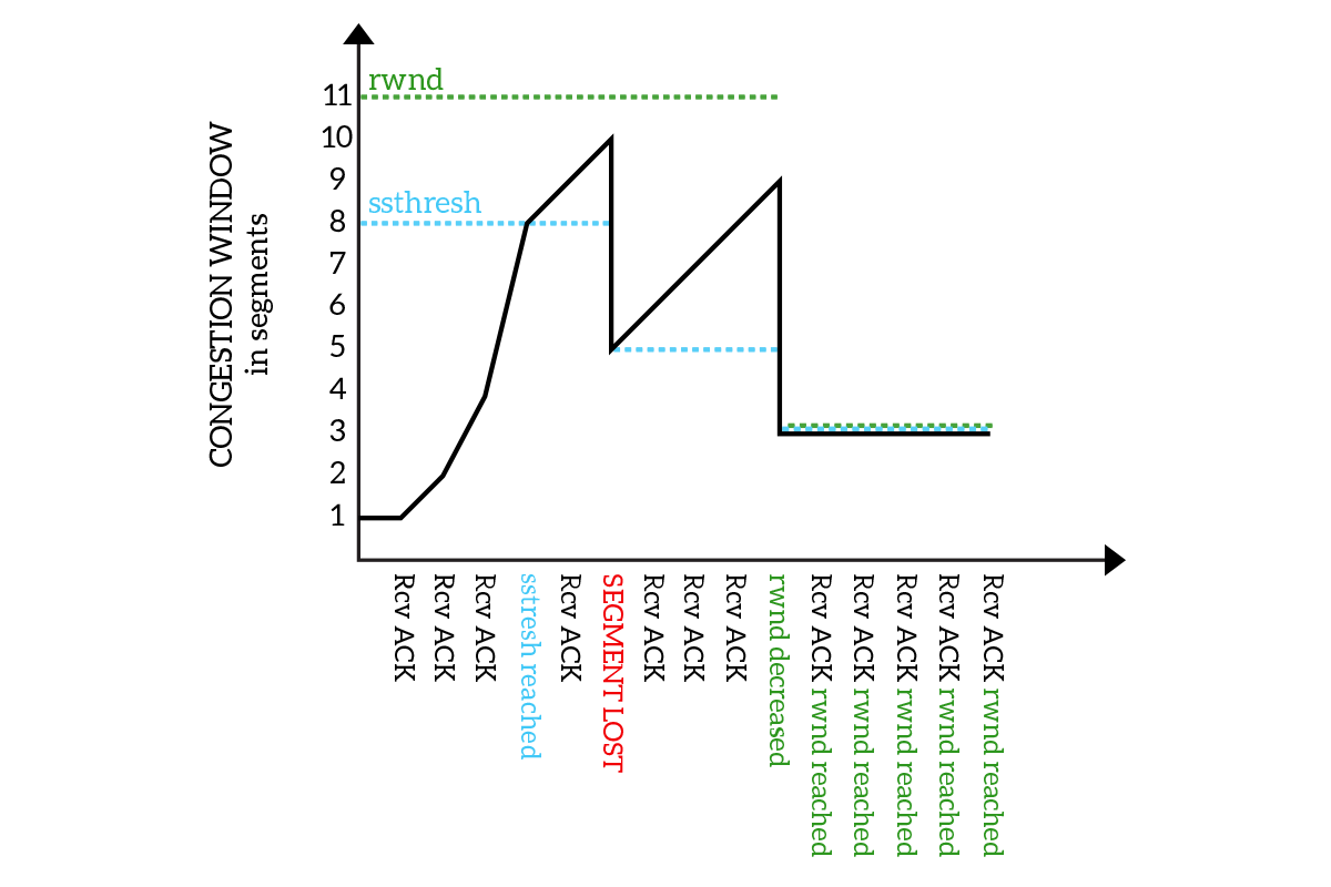
As you can see from the picture, the congestion window starts with the value of 1 segment and keeps doubling (receiving ACKs) until it reaches the ssthresh, then it starts to increase linearly until a segment is lost. Then, the ssthresh is set to half of the maximum congestion window reached, and the congestion window continues to increase linearly from it. Finally, the receiver window is reduced and the ssthresh and congestion window go with it.
UDP predominance and TCP starvation
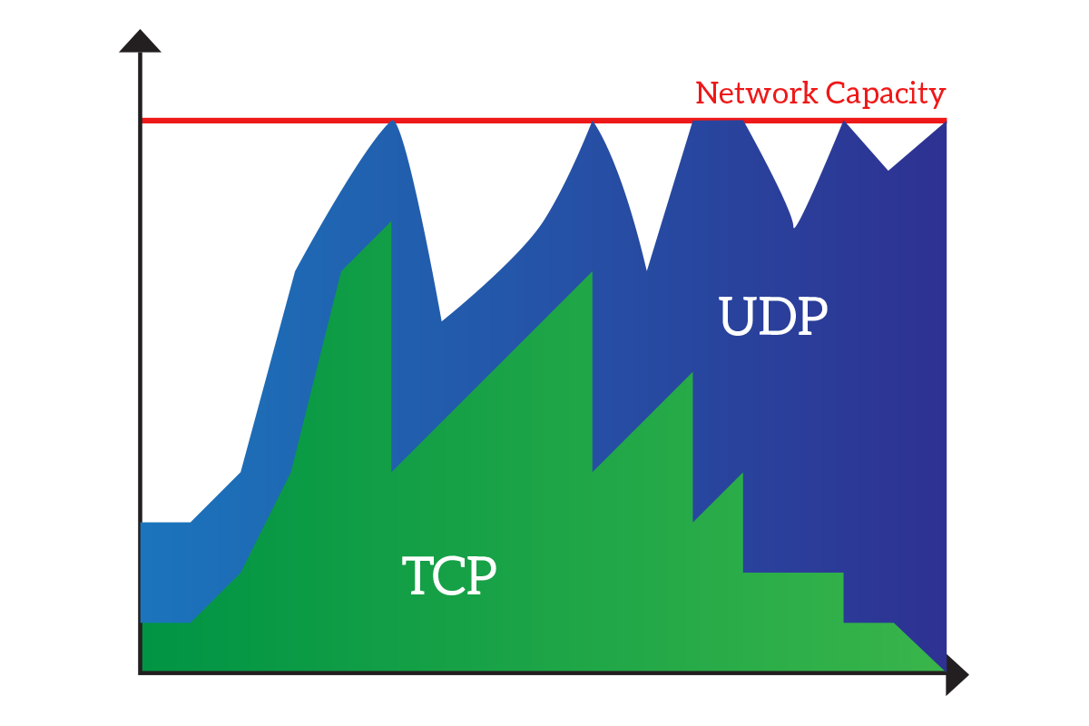
With congestion control in mind, we are ready to talk about UDP and TCP over the same network. TCP implements such a sophisticated mechanism to back-off in case of network congestion, but UDP does not. So, if a lot of traffic is generated in UDP, so much that TCP and UDP together exceed the network capacity, TCP will back-off due to the congestion control algorithm. UDP instead, will continue to use the bandwidth it was already using, and if some UDP traffic was queued due to the network congestion, it will be triggered now that the network is not congested anymore. If this saturates the network again, TCP will continue to back-off until UDP is almost the only traffic in the network. The following chart explains that.
This is not a real problem in the LAN environment when we have high-bandwidth links that are unlikely to get saturated. Instead, on WAN links (connecting sites geographically distant), we must put in place some mechanisms to avoid that these links get saturated with UDP traffic. These mechanisms are known as Quality of Service (QoS), which is a set of rules defining how the network should react when it is congested. These rules are defined on routers and basically define the criteria by which traffic can or cannot be dropped. Keep in mind that when the link is full, something has to be dropped. QoS rules can keep UDP separated from TCP so that UDP can saturate only its part of the network, can grant a percentage of bandwidth for some applications or can even reserve bandwidth to other applications (meaning that this part of bandwidth will be used only by some applications, and in case they are not using it nothing else will be able to use it).
In this article, we covered all the fancy features of TCP. With this knowledge, you are now ready to discuss how TCP works at an almost-CCNP level. Moreover, this knowledge will be very useful to you when talking about firewalls, and you are now in the right mindset to check out what UDP can do and what session and presentation layers are about, as we will do in the following article.


8 Responses
Cool job, thanks for sharing!
Thank you mate! Please let me know if you have any suggestion.
Thank-you so much!
Alexandre for Brazil!
You are welcome Alexandre! Keep coming for other articles like this, and don’t forget to share your views on what you would like to read next 🙂
Great article..really helpful.. do you have more details for TCP IP advanced. Article like what all tcp tunning can be done for optimising the network will be really helpful.
Many thanks, I am so glad this was helpful to you.
Right now I haven’t planned any article diving deeper on TCP, but I could prepare one if this is an interesting topic. However, you won’t be able to tune TCP so much besides the techniques explained in this article. TCP is well optimized, and it addresses applications’ needs. An article diving deeper would be something on how to tune router to handle TCP, and on how to implement TCP in an application (this involves some programming). Would this interest you?
Hello,
I like this article. If you are open to suggestions, I would like to recommend discussing window scaling, max segment size, and timestamps. All very common TCP options that a large number of people dont understand.
Anyways, great work!
Colin
Hello Colin,
I am open to suggestions! I’ve noted that, and I’ll try to insert in my schedule an article about such TCP options.
Thank you, and happy networking!
Alessandro
Comments are closed.