
At this point in the CCNA course, we know that switching is about local communication. Switches connect together devices relatively close: the same office, the same building, and so on. Instead, when we want to connect remote devices together, we need to use routing. Routers sends traffic to other devices based on IP address information. At the core of this process we have the routing table. In this article we are going to talk just about that. We will see how the routing table works, and how to read it.
This article comes with a discovery lab. Use the link below to download it and open it with Cisco Packet Tracer. You will benefit the most from this article if you explore the configuration while we are explaining it. Plus, it’s free!

Once you downloaded it, keep it open and continue reading.
Routing Table lab intro
The Topology
The following image shows the topology of the lab we just downloaded.
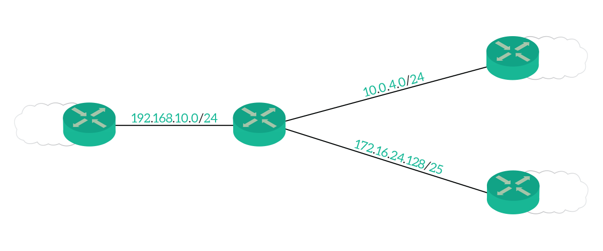
This infrastructure is fairly simple, as it contains only four routers. The center router, named R0, has a cable going to all the other routers. Each of them has some other networks attached (the clouds). However, if you open the Packet Tracer, you won’t see those clouds. This is because we are emulating networks through the usage of loopback interfaces.
The concept of the loopback interface might be new to you. Luckily, it is very simple. A loopback interface is a virtual interface you can create on routers and (some) switches. Therefore, it is only a logical item completely managed at the configuration level. You can create and delete multiple loopback interfaces, at will. Considering that, loopback interfaces come handy when you have to do demo and lab, like now. Moreover, you can use them as management interfaces. For example, a router has several interfaces with different IP addresses. To avoid confusion, you can create a loopback and assign to it the IP address of the router itself.
The Requirements
Since this is a discovery lab, you won’t need to do any configuration or troubleshooting. Instead, just connect to devices and check configuration, or try show commands. All in all, there is no requirement for this lab.
The way a Router works
The logic behind the Routing Table
The task of each router is clear: send traffic to the correct destination. To do that, routers leverage their routing table. The routing table is just what the name says: a table. That table, in reality, is a list of routes. Each route indicates a destination subnet, as well as how to reach it. Specifically, there is only two pieces of information that tell the router how to reach a destination. They are the next-hop and the exit interface.
Every packet received by the router will be forwarded according to the information present in the Routing table.
The next-hop is the IP address of a contiguous router. In other words, if two routers are connected to the same Layer 2 broadcast domain, they are contiguous. With that information in the routing table, the router knows that for that target subnet traffic will have to go to that next-hop. Note that the router does not know what will happen to packets after they reach the next-hop. It just knows that they must go to it (for that given destination). We use the next-hop in routes when that next-hop is on a shared segment, like ethernet links.
Instead, we can use the exit interface when we have point-to-point links, like Serial. This way, we tell the router just to send traffic out of a specific interface. Since on the other side, we are going to have a router, and only one, it will get our traffic and process it.
A visualized example
All in all, the routing table looks a lot like a series of statements like “To reach this subnet, go this way” or “You can get there by going there first”. The following picture shows just that, emulating the routing table on the central router.

Have a look at the picture above. The idea behind it is extremely simple: the arrow direction indicates the next-hop, while the content of the arrow indicates the destination. For example, if we look at the bottom arrow, we know that we can reach the 39.164.80.0/24 subnet by going to the router on the bottom right. The central router does not know where exactly this subnet is, it just knows it is behind the router on the bottom right. Another example would be 192.168.0.0/16, which is behind the router on the left.
The Route Lookup process
Overview
We now know that the routing table contains all the information necessary to forward a packet to the correct destination. However, this is only the tip of the iceberg. We need to know how the router uses routing table content.
Before we start to dive into this process, we need to know exactly what each route contains. The routing table is a list of routes, and for each, we have the destination subnet, its subnet mask, and the next-hop/exit interface. To that, we might add some fancy data such as metric, routing source, and more, but that’s for another article.
When the router receives an IP packet, it matches the packet’s header against the routing table. Specifically, the field to match is the destination IP address. For each route in the routing table, the router performs a bitwise-AND between the destination IP address and the subnet mask contained in the route. Not quite sure what does this means? We have an awesome article about bitwise operations. If the result of the bitwise-AND is exactly the target network of the route, we have a match. The picture below explains just that.
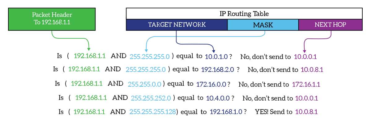
In this example, the destination IP address matches the last route. Therefore, the packet will be sent according to the next-hop specified for that route, which is 10.0.8.1.
Conflicts in the Routing Table
In the routing table, each route is unique. This means that the combination of the target network and subnet mask is unique. As a result, we won’t find multiple routes having exactly the same target network and subnet mask. However, a route may contain multiple next-hop addresses to load-balance traffic between them.
Nonetheless, we might have overlapping routes. With these, one route points to a target network which is already reachable by using the other route. Anyway, in these cases the subnet mask between the two routes is different. The first time you read that, it might seem confusing. But, here’s an example. Imagine we can reach 192.168.0.0/16 by going through R1, and 192.168.1.0/24 by going through R2. If we analyze the first route, we find that it covers any address between 192.168.0.0 and 192.168.255.255. The second route, instead, is for addresses between 192.168.1.0 and 192.168.1.255. These addresses are matched by both routes! In this case, we have an overlap. But don’t worry, this is perfectly fine.
When two (or more) routes match an IP packet destination address, the most specific is used. The most specific route is the one with the longest subnet mask. For example, using the previous routes, a packet to 192.168.1.20 will go to R2, while a packet to 192.168.40.10 will go to R1. Simple, huh?
The Default Route
An interesting case of overlapping routes is the default route. The default route is the last-resort one, the one to use when we have no clue where to send a packet. Generally, it is the one pointing to the Internet. Since we need it to match anything we don’t have a specific route for, it always is 0.0.0.0/0. This will match any single destination in the world, and overlap with all other routes. However, if another route matches too, the router will use the specific route. This is because all routes are more specific (have a subnet mask greater than 0).
Layer 2 Forwarding Information
At this point, we covered all the basics of the routing table. However, in modern routers, packets are not matched against them. Instead, there is another table used in conjunction with the routing table. To understand that, we first need to talk about frame rewrite process.
What is Frame Rewrite?
Routers naturally perform frame rewrite, they have no alternative to do so. Frame rewrite is the process of changing the Data-Link Layer frame header while maintaining the IP packet header untouched.
To clarify that, we can follow a packet along its path. A device generates a packet to a remote network, knowing it must send it to its default gateway. Therefore, it fills the IP addressing information with the target device’s IP as the destination, and it’s IP as the source. Then, it puts that IP packet into an Ethernet frame. For that, it uses its own MAC address as the source, and the MAC address of its default gateway as the destination. The default gateway, which is a router, receives a packet destined for itself at L2, and for a remote device at L3.
Frame rewrite is a direct consequence of routing. A router moves packets between different Layer 2 domains, and Layer 2 information is significant only within the same L2 domain. Therefore, the router must replace them with valid ones. As a result, it will use its own MAC address (on the exit interface) as the source, and the next-hop MAC address as the destination.
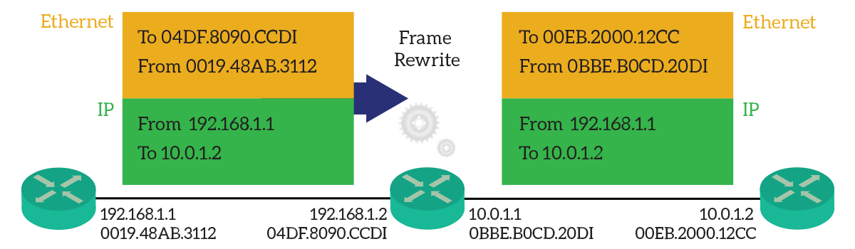
As from the picture, the router on the left wants to send a packet to the router on the right. It must flow through the router in the middle. Note how the center router changes the Ethernet header information, while the IP header remains untouched. Source and destination MAC addresses have changed.
Furthermore, packets may move over different Layer 2 transport (e.g. From Ethernet to Serial), so the entire Layer 2 framework might change. Routers can take care of that by rewriting the frame.
Frame Rewrite Information table
If the router keeps looking at the routing table, every time it detects the correct next-hop, it must create a new Layer 2 header. Instead of performing frame-rewrite on-the-fly, modern routers implement a specific table (in hardware), containing all the Frame Rewrite information needed. We know which routes use which next-hop, and we know that to reach the same next-hop Layer 2 header is always the same. Therefore, the router prepares a Data-link layer header ready for the replacement.
In the Cisco world, this is called Express Forwarding. With Express Forwarding, the lookup happens in the routing table the first time, and all other packets for the same destination are hardware-processed. Furthermore, Cisco devices implement a further enhancement: CEF (Cisco Express Forwarding). With this technology, the router prepares a Frame Rewrite table (the CEF table) before it receives traffic, so even the first packet is hardware-processed. This speeds up a lot the routing.
CEF is active by default on the majority of devices supporting it. If you want, you can turn it off with the configuration command no ip cef. Other vendors implement similar techniques to enhance routing performance.
The Routing Table in Cisco IOS
It is now time to get our hands-on lab gears. Open your Packet Tracer if you haven’t already, as we are going to see how to check the routing table in the real world. You can log into any device you want, and I encourage you to do so but note that R0 (the one in the center) has the most complete routing table. Therefore, we are going to use this one.
How to Read the Routing Table
Showing the entire Routing Table
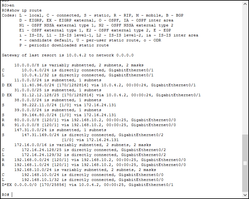
If you want to check the content of the entire routing table on a Cisco device, just issue show ip route. This command is available in user mode (>) and privileged exec mode (#). As a result, you will see the whole content of the table, as well as a legend of codes. Here’s the example output from Router 0.
Breaking Down the Output
At first glance, the output might seem confusing. Don’t worry, it is very easy to get the information we need. First, the Routing Table is divided into sections, which represent a major network. A major network is a classful network, to which we have at least some routes. We can see an example just in the first line of the table, as we highlight below.

In the first line, our router is telling us that the major classful network 10.0.0.0/8 is subnetted. Furthermore, it tells us that those subnets are not all of the same size (that’s for “variably”). At the very left of this line, we don’t have any letters. This means that this line is just a section placeholder, not a route. Instead, for the two lines below, we see a “C” and an “L” on the left: they are routes. We highlighted the destination subnet in light-blue and the exit interface in light-purple.
Here we have another example, this time with the next-hop instead of the exit interface.

If you see “via” in a route, then we are talking about a next-hop. In this case, the subnet 147.31.169.0/24 is reachable through 172.16.24.132.
The routing table is at the core of routers, but in the real world, it can contain tons of routes. Therefore, it might be complex to read it or find what we want. So, just check the next section.
How to Trim the Output of the Routing Table
Any Network Engineer must be very comfortable at navigating the routing table. We need to be able to just see the routes we want. The command for that is still show ip route, but with a little enhancement. This time, we add the destination IP address just after the command. As a result, the router will perform the route lookup process and presents us with the best route (most specific) that matched. Here’s a practical example.
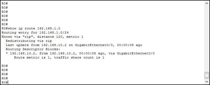
As you can see, here we can find much more information about this route. However, the basics are always the same. We know it is reachable via GigabitEthernet 0/0, by contacting 192.168.10.2. Now, this is very important: in case there is no specific route for a destination, but a default route is present, this command (with the target IP address) will tell you “subnet not in table”. So, be aware that you can use it to match against every route but the default.
Another fancy way to restrict the output is to use the pipe command. For now, we won’t explain all the details about that. However, if you are familiar with Linux, you’ll know that you can use the pipe character followed by some instructions to restrict the output of a command. Cisco is very similar to Linux in that sense. A great way to skip the legend and just see the routing table is by using show ip route | begin Gateway. This way, we tell the router to start to show the output when it finds the word “Gateway”. Note that this is case-sensitive, so “gateway” won’t produce the same output.
The Routing Table is not perfect
The routing table works extremely well. After all, it is so simple. We can expect traffic to go where the routing table says 100% of the time. However, what makes the difference is where the routing table takes its information. The routing table is populated by various sources: connected links, manually configured routes, and dynamic routing protocols. Any wrong configuration to those items may result in wrong routes inserted in the routing table.
All in all, if the router is sending traffic onto a wrong path, it is because we configured it wrong. So, if you see a route in the routing table, you will know that traffic will go this way. Instead, you cannot tell from the routing table if traffic should go that way or not. You just know it will.
Conclusion
Now, take a minute to become familiar with the routing table in the Packet Tracer you downloaded. In this article, we covered all the basics you need to work with the routing table, and – most importantly – the logic behind it. Just as a recap:
- The routing table contains routes, which instruct the routers on where to send the traffic
- Each route has a target network, a subnet mask and either a next-hop or an exit interface
- In the routing table, two identical routes cannot exist, but two (or more) overlapping routes can
- Routers perform Frame Rewrite when doing the routing to adapt the Layer 2 Frame header to the new network segment
- CEF (Cisco Express Forwarding) caches the Frame Rewrite information, you can turn it off with
no ip cefcommand - Use
show ip routeto check the content of the routing table
Take all the time you need to review this article. Not only these concepts are extremely useful when you are working, but they are very important in the certification too! Once you are confident, continue with the CCNA course and discover the other side of the routing table!


One Response
Hello Alessandro,
Just wanted to make you aware that when I was trying to download the lab for this lesson, I encountered a Failed – Network error message on my MAC and in a Windows environment, same error. Thanks again, love the content and accompanying labs!
Comments are closed.