
If you come from the previous article, you know what PPP is and how does it work. The Point-to-Point Protocol is a good Layer 2 protocol that allows two peers to talk directly. Furthermore, it negotiates some parameters before considering the link up, including authentication. However, PPP runs on serial links only. With PPPoE, we overcome this limit by encapsulating PPP into Ethernet frames. Welcome to the world of Point-to-Point Protocol over Ethernet, which brings the befits of PPP on Ethernet links.
This article introduces some new configuration commands. Unfortunately, Cisco Packet Tracer doesn’t support all of them, so that we can’t create a full lab. Don’t worry, however, these commands are easy to use and easy to remember. For the server-side commands, instead, we have a great lab that you can download with the link below.

Download the lab and un-zip it, then open it with Cisco Packet Tracer. Then keep it for later use, you will configure a PPPoE server later on in this article.
Introducing PPPoE
Why PPPoE?
We know from the introduction that we want the benefits of PPP in Ethernet links. That’s right, but you will see we just want one benefit in reality. In fact, we cannot leverage compression or low-overhead: putting PPP inside Ethernet means doubling the headers. This results in adding the small header of PPP to the Ethernet’s header, reducing the available space for “useful data”. Even link negotiation would be fake, as we could just use Ethernet and skip the negotiation.
There’s just one thing we want: authentication. We use PPPoE to authenticate our peer on an Ethernet link, and this becomes useful if the peer has no serial interface. This is often a good approach for connecting to the ISP. In this case, you have a modem that bridges the Ethernet signal on a serial link. The modem is just transparent, it merely converts signals and layer 2 protocols, like a switch. Instead, it doesn’t change IP addresses, nor check them to perform routing. So, it just relays traffic to your ISP (back and forth). This means that you can connect to your modem any Ethernet-enabled device, and your ISP will ask it for authentication.
You can use PPPoE to connect directly a PC to the modem (and to the Internet), or as a WAN uplink in a router. We often use PPPoE in combination with DSL connections, like ADSL.
PPPoE client and server
PPP works with peers. With that protocol, two routers are equal, and they authenticate each other. PPPoE is slightly different, as it implements a Client-Server approach. Of course, the ISP will be the server and your router or PC will be the client. The reason for that is that you are asking the ISP for a connection, and the ISP serves you. With PPPoE, the ISP will never initiate a connection toward you. Instead, you have to make the first move.
For the CCNA, you need to configure PPPoE clients, as this is a common real-life scenario.
Configuring PPPoE Client
We can group the PPPoE client configuration in two parts. The first (and smaller) one happens on the Ethernet interface, the other on the dialer. If you don’t know what a dialer is, don’t worry: we will explain that later.
Configuring the Ethernet interface
Before you start, you want to connect the Ethernet cable coming from your DSL modem in any free port. Then, we need to configure that port: in our example, it is the GigabitEthernet 0/0. On this interface, we need to enable PPPoE and associate it with a dial-pool. Cisco identifies the dial pools with numbers, and none is present on the router by default. So, we are going to use dial-pool number 1. Below, all the commands to type.
interface GigabitEthernet 0/0
 pppoe enable
 pppoe-client dial-pool-number 1
exit
Up to this point, we are telling the router to not use simple Ethernet on this interface. Instead, we are telling to use PPPoE, and that the PPPoE configuration is in the dial-pool number 1.
Configuring the Dialer, basic settings
The Dialer is a logical interface that represents the termination of the PPPoE connection. The Ethernet interface just connects the underlying Ethernet link that encapsulates PPP frames. Instead, the dialer uses the encapsulated PPP. As a result, we are going to use the dialer for all the PPP-specific features, such as authentication. And, on top of that, even for forwarding traffic: routes will use the dialer interface, not the Ethernet interface.
To configure the dialer, we need to create one and identify it with an ID. As a best practice, use the same ID of the dial-pool number, as below.
interface Dialer 1
Once you are in the interface configuration, you need to adjust some settings. First thing, we set the encapsulation to be PPP. Then, we adjust the MTU considering that we are using twice the L2 head as normal. If you remove the bytes of the PPP header from the Ethernet payload, you will see that the MTU now is 1492. PPP is able to assign an IP address to the target device, and ISPs will do that many times. So, we will tell the router to use the address given by the ISP.
encapsulation ppp
mtu 1492
ip address negotiated
Configuring the Dialer, PPP authentication
At this point, we want to bind this dialer to the Ethernet interface and specify the authentication settings. To do the binding, we associate the dialer to the same dial-pool of the Ethernet interface. Note that the command here is different: dialer pool instead of pppoe-client dial-pool. Then, we specify the authentication method (pap and chap, either with dial-in or call-in). Don’t worry about that, your ISP will tell you which one to use. You will have to provide your username (hostname in the configuration) and password, as your ISP will tell you. Normally, usernames are in an email-like format.
dialer pool 1
ppp authentication <pap|chap> <dialin|callin>
ppp <chap|pap> hostname
ppp <chap|pap> password
exit</chap|pap></chap|pap></dialin|callin></pap|chap>
At this point, you have a functioning Layer 2 PPPoE link. In case it doesn’t work, you can debug with the same commands of PPP. For example, use debug ppp authentication, or use the new debug pppoe events.
Adding routes
Now, you can use the dialer like any other interface. A common application for that is having a default route to the Internet which goes over the PPPoE link. To add that, you can use ip route 0.0.0.0 0.0.0.0 dialer 1. Remember to add NAT and some basic ACLs to protect your network from outside attacks.
Configuring the PPPoE Server
PPPoE Server Lab Introduction
The Topology
For this lab, we have two clients connected to a router via a Modem and a DSL connection. The router terminates the DSL connection and will have to terminate the PPPoE too, acting as a PPPoE server.
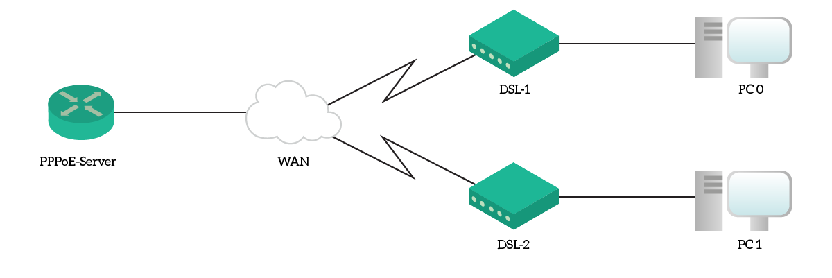
So, we are going to configure only that router, and use the clients for testing the connection.
The Requirements
Our goal is simple: the router must serve as a PPPoE Dial-in server for the clients. They must be able to initiate the connection themselves, using PPPoE. To allow that, we will create two users: cst-001 and cst-002, both with password ictshore. The router should have an address of 84.3.98.1/29, and must give addresses from .2 to .6 to clients.
Configuring a PPPoE Server
Usernames and address lease
We will start this lab by configuring usernames. For the CCNA, we need to know how to install PPPoE servers with local authentication. Therefore, we will create two new users on the router, as by requirement. To do that, we need to use the username configuration command, like below.
username cst-001 password ictshore
username cst-002 password ictshore
Then, we need to define which addresses will the client get. We can’t bind a specific address to a specific username, but we can create a pool instead. This looks a lot like a DHCP pool, but this time PPP will assign addresses. For our lab, we want to create a pool named “PPPoE-Dialers” which starts from 84.3.98.2 and ends with 84.3.98.6. We can do it with the command below, which expects the pool name, the start address, and the end address.
ip local pool PPPoE-Dialers 84.3.98.2 84.3.98.6
The Virtual Template
PPPoE are point-to-point connections. However, we defined a pool of addresses, typical of a broadcast network, like plain Ethernet. This is not a problem, thanks to virtual templates. A virtual template is a special type of virtual interface on a router, which represents the PPP connection over PPPoE. In other words, when the client establishes the connection to the server, the server will create dynamically an interface to represent the connection. The parameters of this interface come from a template: the virtual template interface.
So, we enter the configuration of the virtual template 1 by typing interface Virtual-Template 1. From there, we need to specify the connection settings. With ip unnumbered, we tell the router to use the IP address of another interface, instead of a dedicated one. We will use the GigabitEthernet0/0, which faces the WAN. Then, we specify the addresses to give to peers, and finally that we want to authenticate with CHAP. Here are the commands.
interface Virtual-Template 1
 ip unnumbered GigabitEthernet 0/0
 peer default ip address pool PPPoE-Dialers
 ppp authentication chap
 exit
The VPDN Group
VPDN stands for Virtual Private Dial-up Network. In other words, a network where clients dial-in to initiate a connection to the server. We need to enable this feature on the router with vpdn enable global configuration command.
Then, we need to define a VPDN group (which we will name “GROUP”). This associates the VPDN feature to the Virtual-Template we created, using PPPoE. Note that we bind the protocol and the template to the “accept-dialin” feature.
vpdn-group GROUP
 accept-dialin
  protocol pppoe
  virtual-template 1
Now, we would need to do something else. In real life, we need to type the following commands to associate the PPPoE group to the virtual template. However, Packet Tracer doesn’t support that, and automatically generates the command below.
bba-group pppoe global
 virtual-template 1
 exit
Configuring the Physical Interface
The last thing we want to do is the physical interface configuration. We just need to give it an IP address and enable PPPoE, as below.
interface GigabitEthernet 0/0
 pppoe enable
 ip address 84.3.98.1 255.255.255.248
Congratulations! You have now finished the lab, your score should be 100% by now.
Verify the PPPoE Dial-in
If you want to verify that things work, you can log into any of the two clients. Then, from the desktop tab, select the PPPoE dialer as by the screenshot below.
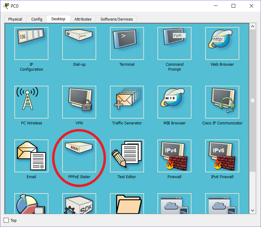
Then, type your credentials and click connect. You will get a message saying that you have established a PPPoE connection. After that, you can ping 8.8.8.8, or type ipconfig to see your configuration. Instead of having an IP address on the Ethernet interface, you will see one on the PPP adapter.
Conclusion
In this article, we covered all the beauty of configuring a PPPoE client. Now, you should be able to connect to a DSL or Cable provider using this technology. On top of that, you will have a better understanding of this protocol, knowing what to do when using it from the PC. We won’t report all the configuration commands in this conclusion, as the article was pretty dense. Instead, we will recap the key concepts you need to take with you.
- Configure a PPPoE client
- Enable PPPoE on the Ethernet interface and associate it to a dial pool
- Create a dialer interface and define the encapsulation (PPP), MTU, and how it will get the IP (generally from the provider)
- Associate the interface with the same dial pool as the ethernet interface, then define PPP authentication settings
- Configure a PPPoE server
- Define the usernames, then define the address pools for clients
- Create a Virtual Template interface where you will define the PPP connection settings, like authentication
- Enable VPDN and the accept-dialin feature, then bind it to PPPoE (automatic in Packet Tracer)
- Configure the Ethernet interface facing the WAN to support PPPoE and to have an IP address
Now that you are into nested encapsulation, we will take you ahead with your CCNA by explaining some other tunneling protocols. Just continue with the Free CCNA course.


8 Responses
Hi Alessandro. Thanks for the free course. Its direct and very useful. However, I am finding difficulties following this PPPoE tutorial. Some commands aren’t working, like the “pppoe-client” command. Searched online and I also discovered other ways people are configuring PPPoE. Is there a standard way or you have to do what you are comfortable with?
Hello Steven, many thanks – I am happy you are liking the course.
Unfortunately, PPPeE is an hard topic, and not because of the protocol itself. In fact, PPPoE is a quite simple protocol, but its implementation is not straightforward. Commands changed from version to version in IOS routers, and this is why you are going to find different many different tutorials to do the exact same thing. On top of that, Packet Tracer features are limited to only a minimal part of the PPP-related commands, and this doesn’t help either.
Since you are going to use PPPoE to connect to the Internet in the real world, providers will tell you the settings you need. Even more, some providers may give you the exact commands for Cisco routers, as these routers are widely adopted.
In the end, to answer your question, it is not about being comfortable, it is about IOS version. In case you struggle with Packet Tracer, try with GNS3 – you might have the commands here. But, if you don’t, don’t worry too much. Just ensure you get the concepts of PPPoE right (like the encapsulation of PPP over Ethernet).
Alessandro Maggio i am following your website . you had write some best article but this is confusing .
Thank you Amar, I really appreciate that.
About this article – I know it looks a little bit messy. A lot of stuff is thrown at you, without a clear explanation on all the details. Unfortunately this is exactly how the CCNA Curriculum treats PPPoE: a lot of commands, many of them a little bit “obscure”. I could expand the explanation of PPPoE, for that we would need several article to cover everything. On top of that, we can forget Packet Tracer – it simply does not implement that.
Fortunately, the CCNA certification does not require you to know a lot about PPPoE, so my suggestion is ensure you can set up a lab in packet tracer like the one here and practice it a little bit. If, somehow, you manage to make it work, it will be more than enough for the certification. I would say that PPPoE accounts for less than 1% of the total exam, in fact when I took the exam a few years ago I had no question at all on PPPoE.
After enabling vpdn and vpdn-group GROUP, when I run the command “protocol pppoe” I get an error saying “This command is not supported by Packet Tracer” What should I do? Is it possible to setup a PPPoE server without this?
Which version of Packet Tracer are you using? I know there are many limitations in Packet Tracer regarding PPPoE, so not all configurations may be available.
I am running into the same problem. I am running Version 7.2.1.0218. I will start to run the command then put in protocol ? and PPPoe will come in red. I am guessing they took the ability to run this command off.
I will see if is still works without that command or is there some other way I should try to practice this network.
Unfortunately packet tracer has not really a great support for PPPoE. I should revise this lab, but I am not completely sure we can do everything that needs to be done about PPPoE in packet tracer.
Thanks for sharing your experience with the lab!
Comments are closed.