If you are reading this article coming from the CCNA Course, you already know the concepts of OSI and that, in the end, your information has to be put onto a cable, or over the air, in order to reach the destination. How is it possible that complex images, video streams, chat and even more can travel over a simple copper cable, or even through the void? If you want to find that out, you’ve found the right article, because here we talk about how is the information converted into electricity or light: the signals we can find at the physical layer.
Digital vs Analog signals
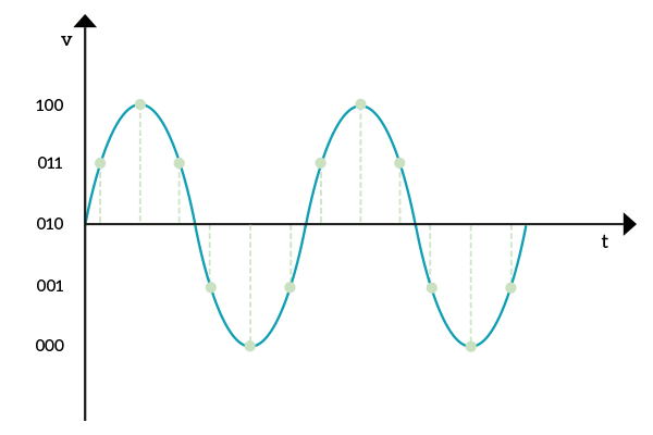
In order to understand the logic behind any data transfer, we must first clarify the concept of digital and analog. The shortest way to say it is that Computers are digital, real-world is analog. With that, we mean that computers work with a “yes or no” thinking process, nothing in the middle. In the real world, instead, we do not have just black and white, but a potentially infinite set of grays. So, if to a human we could have 0.1, 0.2 and so on after zero, to a computer it’s just 0 and then 1. Nothing in between. Of course, a computer can understand dotted digits, but this because they represent their value differently because the memory of a computer cannot understand the indeterminate. This can be a problem when you want to bridge information out of a computer and into another. The information has to travel in the real world, encountering the analog. We will see, later in this article, that information travels in the form of waves. If you measure the voltage on a cable transmitting information, you will find that voltage going up and down over time, in the form of a wave. We must be able to pass digital information using a similar wave and then read it to convert it back to the digital stuff it was.
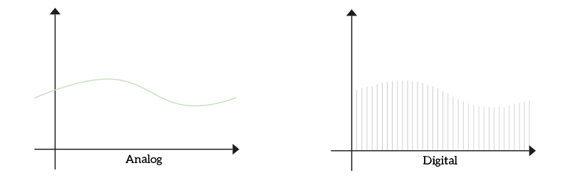
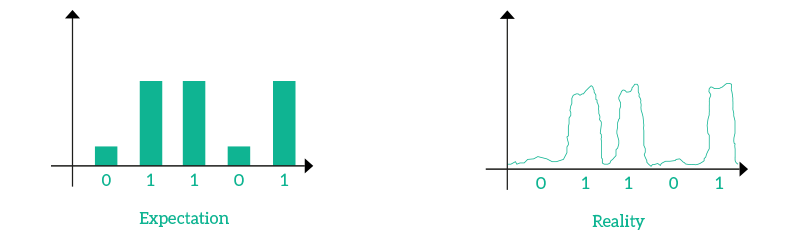
To be even clearer, an analog signal is continuous and a digital signal “jumps” between specific values. What the previous image show is much more than an analog signal and its digital counterpart, it is the process of sampling. The concept is simple: in order to represent an analog signal, we measure it at specific time intervals in order to have an approximate digital version. This is done not only on cables, but in order to digitize your voice during a call, for example. So now we have an idea of how the computer can read the signal it receives, but what about sending information? You cannot reverse the sampling process in order to get an analog wave as is. Since the cable is connected to two devices, these two controls the electricity (and therefore the wave) flowing on it. So you can decide to send a small wave every time you want to send a bit representing one, and send nothing when you want to send a bit representing zero. But it is not that simple, this way what you try to accomplish is to send a signal in pulses, which do not work well with electromagnetic waves. Why? Because you cannot pass instantly from no current flowing to any given voltage: you are in the real world, you have to pass through all intermediary values. Even going back from any current to no current takes you through the same process. Of course, we are talking about instants, but even the smallest instant matters to a computer. Think about that, you can easily find cables working at 1Gbps (1 Gigabit per second) in a modern network. This means that in a microsecond (a millionth of a second) 1000 bits are sent. Even the smallest fraction of time can make the difference. So the idea of sending information in pulses is not a good idea in this case (with fiber optic, instead, it is perfect). The following image shows you the differences between expectation and reality.
So, this method won’t work. We need to find a different solution, but in order to do that we have to understand what a wave is, how it is structured and then how we can use that to our advantage.
Wave and Radiation
In order to get it all, we must start from the very beginning: electric waves. If you give power to an electronic circuit, it will take some instants to reach its normal operating level. You can measure that in Volts (V), which is the difference of electricity potential from a side of the circuit to the other (generally from the plus symbol on the battery to the less symbol on the same battery). When the circuit is disconnected, or open, electricity has no path between the two battery poles, so there is no voltage. As soon as you connect them, electricity will find its path between the poles, and the voltage will increase up to the one specified on the battery itself. We already know that it takes some time for that voltage to make these transitions between states. If we switch on and off the circuit fast and repeatedly we will create an electric wave. A very cool property about electric waves is that if they go up and down fast enough, they become electromagnetic waves, a radiation. Then, these electromagnetic waves can travel in the air, in the void and in solid materials. This is a good news for us, wanting to be connected everywhere.
In order to represent an electric or electromagnetic wave, we lay down two axis, the horizontal one for the time and the vertical one for the voltage. As the time passes, the voltage increases up to a peak, then decreases back to zero, continues to decreases to a trough and then revert the direction. This process repeats indefinitely over the time, provided we have a device generating that wave constantly. Fortunately, we have electric circuits that can create perfect analog waves as the one in the picture.
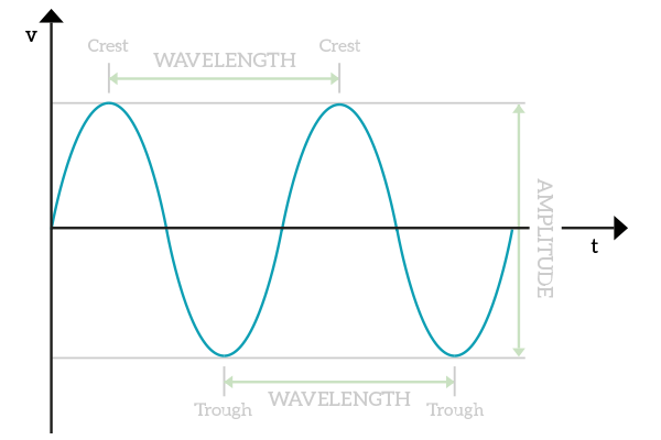
For all the terms you find in the picture, you can find a clear explanation right below. Please note, the voltage is always measured in Volts (V) and the time is always measured in seconds (s).
- Wave – a repeated oscillating signal
- Crest – the highest voltage a wave has
- Trough – the lowest voltage a wave has
- Amplitude – difference, in voltage, between crest and trough
- Wavelength – Distance, in time, between two consecutive crests or between two consecutive troughs
- Frequency –
1 / wavelengthhow many wavelengths can fit in a second – in other words, how many times the wave is repeated in a second
Now that we understand the concept of frequency, we can also understand that light is a wave. All in all, the light is nothing more than electromagnetic waves with an extremely high frequency, much higher than other waves. Even when you speak your voice travel in the air in the form of an audio wave, but at a very low frequency. If you think for a moment, you will be able to understand the benefits and drawbacks of different wave frequencies. Higher frequency means faster waves, but if you put a piece of black paper in a light beam you will block it. This does not apply with voice, because of the lower the frequency, the higher the possibility to traverse solid items. Just keep that in mind for later use. Considering these concepts, we can understand that no matter what is the media (a copper cable, a fiber optic cable, the air), if you could inspect what’s happening in it you will always find some waves flowing.
Excluding light and voice waves, and provided that we can generate a constant and reliable analog wave with an artificial circuit, the best way to transmit the signal would be to use that perfect analog wave to carry the signal. Think about that, we have a perfect analog wave going up and down always at the same time, and that due to its nature it can travel fast and far in a cable. If we were to use pulses, the information wouldn’t go far, but this wave can. However, this is just a wave going up and down at the same interval, acting so predictably. We want to manipulate it in order to send information to the other side. This is where modulation happens, as we will find out in the next section.
Modulation
Modulation is the name of the technique allowing digital information to be transferred over an analog media. To be more specific, modulation is the process of manipulating a carrier wave according to a digital signal. The carrier wave is just a simple analog wave that goes up and down always at the same interval, repeatedly and constantly. It is generated by an electronic circuit that does just that, it has to be perfect. Then, we modify that wave to send information. For example, we can increase the frequency or the voltage. The device on the other side, expecting the perfect original carrier wave, will be able to see what you have modified and therefore read the signal. Modulation is very useful because we have to send bits (zeroes and ones) over an analog media, and we can manipulate the wave based on these zeroes and ones.
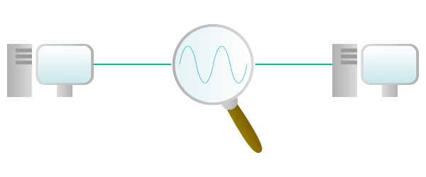
The easiest modulation type to explain is the amplitude modulation: we modify the amplitude (the voltage) in order to represent a zero or a one. Generally, the normal voltage of the carrying wave is zero while a higher voltage over crests or a lower voltage below troughs represents a one. Take a look at the image below.
On the other side, the device expecting a “normal” carrying wave will detect the changes in voltage and detect zeroes and ones, being able to reconstruct the original digital message in binary numbers. Think for a moment about amplitude modulation, where have you already seen these two words? Yes, an AM Radio uses this technique to send voice and music over the air.
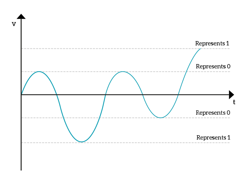
Another widely used modulation method is frequency modulation. In this case, the voltage is untouched and we modify the frequency of the wave. If we want to send a zero, we leave the carrier wave as is, but if we want to send a one we speed up the wave. We force the wave to go up or down faster to represent a one, reducing the wavelength and therefore increasing the frequency.
When the device on the other side receives a crest or a trough before the expected time, it knows that it has received a one, otherwise a zero. Just like amplitude modulation, frequency modulation is used for radio streams, here we have the FM Radio.
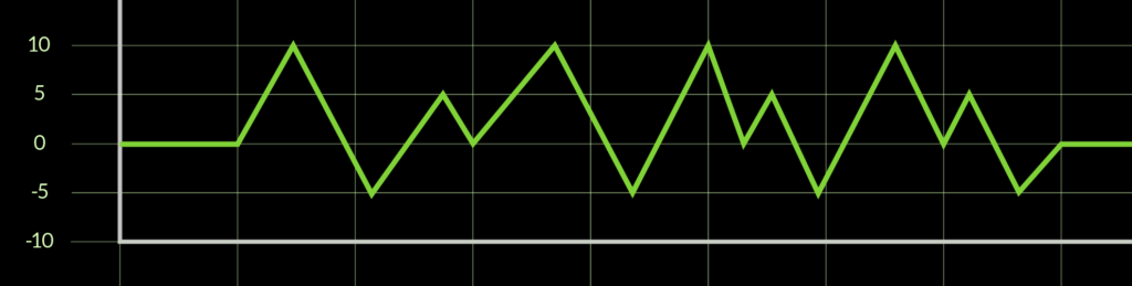
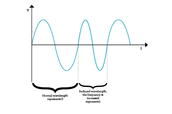
Now it’s time for the masterpiece, the pulse coded modulation. This modulation is the most complex one, but it is the one allowing us to send more combinations at the same time. If with amplitude or frequency modulation we could send only a zero or a one (two combinations) each time, with this technique we can send more combinations within a single wavelength. What we have to do is to take the carrier wave and sample it at regular intervals, defining some specific points on that wave. The wave is sent repeatedly and constantly, so each time it is repeated the receiving device will face all of these points on the carrier. What we have to do is to send a pulse when we know that the other device is receiving a specific combination. The pulse has the function of saying “Hey, receiving device, this is the combination I want you to receive!”. Therefore, for each wavelength we can send a single pulse, which is used to allow the device on the other side to read the combination. The picture below shows how the carrier wave is sampled.
Now, pulse coded modulation is not used for radio transmission, but it is widely used in ICT to transfer bits. More than that, it has been designed specifically to send digital information, because of its nature of sending combinations. The previous image is an example, but we can have even more combinations within the same wavelength, optimizing the process of sending data. Of course, what we want to do is to have a number of combinations that is a power of two, this way we can represent any combination composed by a given numbers of bits in a single wavelength. 8 combinations would be great, because with them you can represent anything within 3 bits, sending 3 bits at a time. 10 combination wouldn’t be so great, instead, because you have to use 4 bits but you are not able to represent all the combinations of 4 bits (that are 16). Given that major advantage of pulse coded modulation, we have also to say that it requires a little more effort to send or receive a signal this way. Fortunately, this is not a problem nowadays.
Now that we explained the three most famous modulation types, it’s time to face reality. Reality can be tough from time to time, and it is if we want to send information. The real world is full of distractions, or to use the technical term, interferences. A lot of things generate electromagnetic waves: cables carrying electricity, TVs, microwave ovens or even dishwashers. To that, we should add devices that are designed to send waves over the air like phones and antennas. All these factors can accidentally modify a wave sent over the air or even in a copper cable. If we are not able to identify interferences promptly, we will mess up all these signals together. Fortunately, we deployed several techniques to detect interferences over time. The first thing we want to do is to have a signal that can send multiple combinations at the same time, such as with pulse coded modulation. We can also combine modulation types together: for example, if we use amplitude and frequency modulation together we can say that low voltage and low frequency represent 00, low voltage and high frequency represent 01, high voltage and low frequency mean 10 and high voltage and high frequency are the 11 combination. More than that, we can also combine amplitude, frequency and pulse coded modulation together, reaching a significant number of combinations. Once we have many combinations, we can define a constellation. A constellation is just the set of values that can be sent in a single wavelength time span. The more values you find in a constellation, the faster the transmission can be (more data can be sent at the same time). To represent a constellation, we use two-axis representing the values we are combining, such as voltage (V) and frequency (Hz).
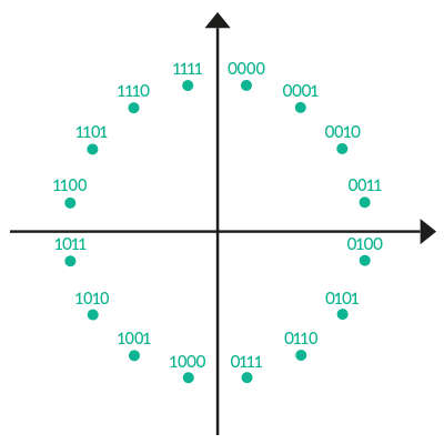
However, with a constellation, we found a way to increase transmission speed, but not a way to identify if the message was disrupted by some interference along the path. The good news is that if we are willing to sacrifice some of the data transfer speed, we can use constellations to identify errors during the transmission and even correct them. Generally, when a value you sent is disrupted by interferences, it is changed to a nearby value: the interfaces do not completely disrupt your signal, but they slightly modify it – enough to make it impossible to read. Since this is true most of the time, we can decide that half of the combinations within a constellation will not be used to represent data. More than that, we alternate a valid value with an invalid one. Obviously, we are going to send only valid values, but if an interference disrupts one of them it will end up being invalid (because each valid value is contiguous to two invalid values). On the other end, the device will receive a non-acceptable value and will know that the message has been disrupted during the transfer. If we detect a failure during the transmission, we can arrange retransmission. But we might want to do more, we might want to be able to restore a disrupted signal. Within a certain limit, this can also be done with constellations. If to identify an error we separated each valid value with an invalid one, this time we separate each valid value with two invalid values. Yes, in the constellation you are going to have one valid number, followed by two invalid numbers, then another valid number, and so on. This way, when a value is disrupted, we can identify uniquely which is the closest valid number and assume that this was the one that the sender originally sent.
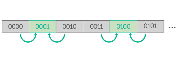
Depending on the balance we want to achieve, we can add more “invalid” numbers sacrificing speed or use just a few of them, sacrificing reliability. No matter which option we want to use, a way of checking errors is always implemented at the OSI Data Link layer (you can find a refresh on the OSI model here), while re-transmissions may be handled at the session layer. A question you might ask is the following: if some numbers are considered invalid, how can we send these numbers? Well, we have to re-map these numbers. Let me explain, if you have 16 combinations you can sacrifice half of them into invalid numbers, then you have 8 valid numbers. To position these 8 numbers in the constellation, you just skip invalid positions. Then, for each invalid position you associate either a valid number (if you want the correction back to a number) or just nothing, meaning that the information is not restorable. A common approach is to put one valid number, one valid number than correct back to your valid number, nothing, then an invalid number that corrects to the next number, then the next number. This way, if the signal is so disrupted to reach the middle ground between the two valid values, it is discarded. If it is disrupted slightly, it can be restored.
Now that we achieved ninja skills on sending and receiving signals, a single piece is still left out of the picture. How can devices start to communicate? How can they detect that a message is coming in the first place? That’s what the next section is all about.
Types of signals
Two different technologies are used to detect when it’s time to listen to what is coming onto a cable: synchronous and asynchronous transmission. At a first glance, you might think that you could just send nothing (like turning the cable off) by not generating a carrier wave, then generate it only when you want to send data. Another option is to maintain your carrier wave at the same level until you want to start to send something. These are valid approaches, but they do not consider interferences. In the first case, interferences may induce the receiver to think that something is coming, but in reality they are only interferences (noise). In the second case, what if our data sequence starts with a series of zeroes? They won’t be noticed. We need to find a better solution. As we said before, we have two options, depending on our needs. In order to understand them, we need to refresh the concept of clock in IT. The clock, in a computer, is the circuit that tells the computer to do its calculations and measurements periodically. Each time it sends a signal, a step in calculations is made, then we wait for it to send a signal again. It has to be very fast and precise.
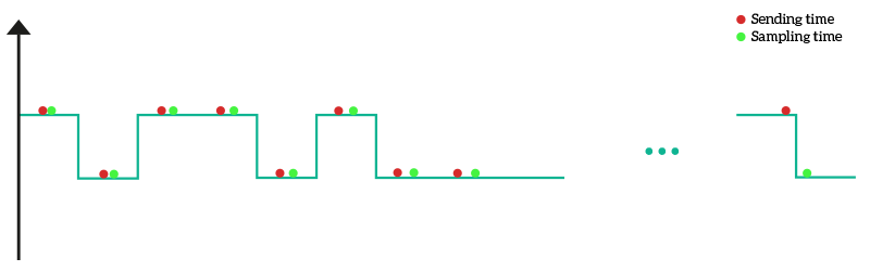
Note: to make examples as clearer as possible, the following images will show only squared waves. A squared wave is just the logical representation of the signal we want to send, before it is combined to the carrier wave. In that wave, you find zeros and ones, with immediate transitions between these states. All in all, is just a wave to represent a binary number in form of a wave (flat crest means 1, flat trough means 0).
In synchronous transmission, both sender and receiver have a synchronized clock. This way, when the clock of the sender decides to put data on the cable, on the same instant the receiver decides to fetch them from the cable. This way, we are sure that the receiver will measure the voltage on the cable exactly where we want it to do so. As in the picture below, clocks are not exactly synchronized, but they are close enough to be considered equal. However, since a small offset between sender and receiver exists, each bit send that offset increases so, after several bits the clock of the receiver may end up being in the next or previous wave, fetching wrong information. To avoid that, with this type of transmission we send only a few bytes at a time, then again after a pause. Generally, we send a “1” to say that the transmission is starting, then just the data we want to send. We do not have to develop complex strategies for the message to begin, so this is a simple and fast method, but that becomes unpractical for long messages. Because of that, this method is mainly used inside a computer, to allow internal components to talk with each other.
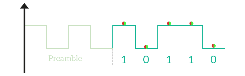
Asynchronous transmission is a little more complex. With that, we want to send more than a thousand bytes in the same message, so the clock must be perfectly synchronized. Therefore, before we can start sending our data, we must do something to ensure that the clock is and remain synchronized. To address just that, we have the Phase Locking Loop (PLL), a technique that tweaks the signals to allow the receiver to synchronize to it. In other words, the clock is sent along with the message. The first thing a PLL does is a preamble, a set of bits flapping up and down (such as 10101010) that allow the receiver to synchronize by detecting the interval between a zero and a one. After the preamble ends, we can start sending our data. The next thing a PLL does is ensuring that the clock stays synchronized. To do that, it twists the message after every several bytes in case it is flat (it does not allow a long series of zeros and ones, because the receiver would be likely to lose the clock). PLL has very advanced techniques to represent a flat sequence of bits with a more twisted one. However, modern PLLs allow an even flat sequence of 64 bytes because they are extremely precise. For its nature, the asynchronous transmission allows the exchange of long messages and due to the reliability added by PLL techniques, it is the one we use when we want to transmit data to a remote device.
Now that we know all these technical information about signals, we are ready to understand the benefits and drawbacks of any media, from different types of cables to the transmission of data over the air. More than that, we have developed the skills and tools needed to evaluate a media and to truly understand everything related to it. For detailed knowledge of cables and medias available in modern (and not so modern) networks, just continue the CCNA Course.


2 Responses
In first place, thank you very much with these courses. I am in the 5th year of telecommunication enginnering and sometimes I feel so stupid because this basic concepts. There is a lot of information in the internet and you filtered it in a very good way.
1-So let me see if i get it:
We always send the information in an analog way but what defines if the signal is analog or digital is the way that we process it in the end of the cable ( in the case of digital eu use pulse code modulation) . Am i right?
2- In the pulse code modulation, we send a pulse during a period of the wave to understand which combination we are sending, right?
My question is, how we send the pulse? Do we send the pulse using the AM modulation or FM modulation?
Thank you very much and great article.
Dear Pedro,
I am really happy to provide you great content, so keep reading it as it is the best way to thank me. Now, let me answer to your questions:
1 – Yes, you are totally right. In the end, the signal must be analog as the “real-world” can understand only analog. There is no such thing as “no electricity” and then “electricity”, but an increasing and decreasing voltage.
2 – Pulse coded modulation is very tricky. What you use, as underlying technique, may vary from circumstances. In fact, it can be achieved with either AM or FM, the one in use really depends on the circumstances.
Now, don’t worry if you sometimes struggle with the basic concepts. If you are going to work in networking, you aren’t going to need to remember all of that, not in such details at least. I hope I was able to help you!
Comments are closed.