
When you have to connect two devices together you have a lot of options, and a copper media is certainly one of them. Copper has some unique properties that make it ideal to craft some specific types of cables, that have specific applications in the real world. In this article we will learn what are the cables that use electromagnetic signals over copper to transfer information, explaining the structure of each cable and what are the benefits and drawbacks of using it in your solution.
Copper Media
Copper is a fantastic metal in conducting electricity. Because of that, back in the 19th century, nations started to lay down thousands of miles of copper cables to support the development of the telephone network. When electricity traverses a solid material, it is somehow blocked by that material, which tries to resist to the passage. Copper is a formidable conductor and allows almost all the electricity to pass. Because of that, copper cable was perfect to allow a telephone call to travel for miles. About 150 years later, we are still using copper media to deliver Internet content right to your computer. Of course, we developed more advanced technologies such as fiber optic, but we still use copper-based technologies most of the time. This is because copper is relatively cheap and fast enough. In other words, a great compromise.

When considering the cost of a technology used to connect two devices, the first thing you might think about is the cost of the cable. Cables have a price per meter, but this is not the only thing to consider. Another important element in the balance is the cost of the NIC (Network Interface Card): each device must have a port to insert the cable into, and that port is connected to a specific circuit that allows the device to communicate using that cable. That circuit is called NIC, and its price varies based on the cable it has to control (copper-based, fiber-optic, wireless antenna, and so on). So you now have considered the cost of the cable and of the two NICs (one per device), but we can go even further. With what we just said, we can tell how much will it cost to connect two devices together, but this is not enough. We want to know how distant can we put these two devices and how fast they can exchange information.
The first item to include in our calculation is the bandwidth. The bandwidth is a property of each communication media (cable, wireless technology) and defines how many bits can be sent over that media in a second. Therefore, it is measured in bits per second (bps) and multiples. This way you can define how much will cost a certain data-transfer speed, and in case you want more you could always use two cables (each cable with its pair of NICs). If you do so, consider that you will double the bandwidth but this will be true only for different traffic. In other words, you can stream two videos at the same speed as you were streaming one, but you cannot stream a single video as twice as fast. The last item you want to consider is the distance that a cable can travel. The more information travel on a cable, the more it becomes disrupted and difficult to read. Because of that, each cable is tested and a certain distance is granted for the data transfer. For example, fiber optics are the only cables that can travel for several miles, but they are the most expensive ones. On the other hand, if you want to run a copper cable tens of miles you will need some devices in the middle to amplify the signal.
Defining the relation between cost and benefits for a media, you might also want to consider other elements that are not related to the cost. For example, the diameter of a cable may be crucial if you have limited space, or its flexibility may be important if you have to bend it in order to reach the device. Another thing to consider is the ease of use of the cable: can you cut it the size you want or do you need special equipment? All these secondary factors need to be considered when developing a solution. Now that you know what to consider, you will be able to read about different copper cables and evaluate the pros and cons.
Coaxial Cable
Copper cables are so widespread for Internet connections because the Internet started to use existing cables. The only two types of existing cables that were already laid down to reach every home are cable TV cables and telephone cables. The coaxial cable is the one from television. This type of cable is a set of concentric layers alternating between electric conducting and insulating materials. This complex structure allows optimal insulation from electrical interferences, but it makes the cable harder and difficult to bend.
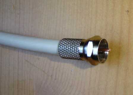
Coaxial cables are used in the USA from some Internet providers using the cable TV infrastructure to deliver the Internet to your home, but their major use today is to connect a device to its antenna. You can these cables in 3G/4G antenna towers, for example. Their structure allows engineers to design bolder cable to carry a higher voltage, delivering even a lot of power to antennas. Because of that, this cable is the one used also to control television and broadcast antennas. The structure of this cable, its most important part, is explained below.
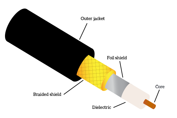
When describing a cable, we always start from the center because this is where the signal is. At the center of the coaxial cable we have a copper core, this is the part of the cable where the signal will flow. The core is surrounded by a dielectric layer, which has the goal of keeping the signal isolated from the outside world. On top of that, we have two shield layers: foil shield and braided shield. These two layers are made of conducting material and, believe it or not, their role is to attract interferences. By doing that, they condense all the interferences on themselves, taking them off the core. In order for these shields to work, they must be grounded: devices with a port for a coaxial cable will connect these shields to the ground so that all the interferences are sent directly to the ground. Finally, outside, we have the jacket, the final insulating layer, generally made of PVC.
All in all, this is what a coaxial cable is. You won’t find much more of it in the CCNA Course and you are not likely to work with it so often, it is just mentioned in the official CCNA Curriculum. Now that we have an overview of this minor technology, we can focus on the real big deal, the Ethernet cable.
Ethernet Cable
Ethernet is the fusion of two words: ether and network. This is because Ethernet is a Data-Link layer protocol that was originally designed to allow communication via radio over the air in the Hawaii islands. That protocol was so well designed that it was standardized by IEEE (reads I-triple-E, Institute of Electrical and Electronics Engineers) in standard 802.3, where they adapted the protocol to work on a copper cable. In order to optimize data transfer and improve both speed and reliability, a specific copper cable was created to carry the IEEE 802.3 protocol. Now, the Ethernet cable is the one used in LAN (Local Area Network) deployments, in other words, it is the one used to connect all users’ PCs together and to the devices that bridge them to the Internet.
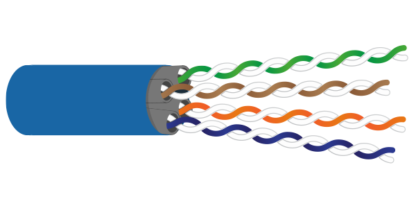
The Ethernet cable is actually a well-crafted composition of several wires. The structure is quite trivial, we have an outer jacket in PVC that contains 4 to 8 individual small wires, each of them with a small individual insulating jacket. Unlike the coaxial cable, which has a single type of structure, not all Ethernet cables are made equal. According to the type of Ethernet cable, you may find four or eight inner wires. If reducing from the standard 8 wires to four wires, you cannot just take out half of the wires randomly. This because each wire represents and carries a specific part of the signal, so it has to be distinguished from the other. However, you should note that the most recent cables always use all the 8 wires to carry more information.

From the previous picture, you can understand that for each colored wire there is a half-white counterpart of the same color. This is because each signal has its positive (colored) and negative (half-white) version. If you cut an Ethernet cable, disclosing the inner wires, you will find that they are twisted together in groups of two: each color with its half-white counterpart. This does not only group them, it has a more practical function. When two wires carrying signals are close enough, they can interfere with one another creating a phenomena called crosstalk. By twisting the wires together, we significantly reduce the crosstalk and we also remove part of external interferences, known as RFI (Radio Frequency Interferences) and EMI (Electro-magnetic Interferences). To leverage on this property, wires are not twisted together randomly, but instead, the number of twists per meter is precisely calculated to remove the most interferences possible. Different cables have specific names according to their structure, and specific categories according to their performance.
The simplest Ethernet cable is the UTP cable. This is the acronym for Unshielded Twisted Pair, and the only protection it has against interferences are the twisting technique and the outer jacket. The simplicity of this type of cable makes it very cheap and versatile. It is a good choice when you do not need high bandwidth. A UTP cable can support signals up to 100MHz, resulting in a bandwidth of up to 1Gbps. This performance allows the cable to be categorized as cat 5e, which is probably the most common category because of the high performances at low prices. This category is just an improvement of cat 5, which may also be used. Every other category previous to that (such as cat 4, cat 3) is to be considered legacy because it does not meet the modern network requirements.

If performance matters, a better cable is the STP Ethernet cable, which stands for Shielded Twisted Pair. As the name suggests, the process of twisting the pairs is not the only technique used to protect information from interferences. Instead, each pair of inner wires is bundled in a jacket and then all of these four inner jackets are bundled together in the cable itself. The inner jackets are generally a foil that keeps interferences away (then the cable is called F/STP, where F stands for Foil). Moreover, in most STP cables, you are also going to find a PVC spine in the middle. This part is less flexible than the rest of the cable and has the role of keeping the four pairs divided from one another. An STP cable can support up to 1000MHz signals, reaching up to a transmission speed up to 10GBps, as in category 7a. You can find a representation of the STP cable right below.
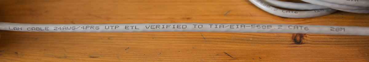
How can you tell the category of a cable? Of course, you can plug it into two devices and try to push onto that cable the more traffic you can, but this isn’t a practical solution. The good news is that information about the cable is printed on the outer jacket every few inches, as in the picture below.
Depending on your needs, you may want to opt for a cheaper cable or for a high-bandwidth one. To help you in the choice, consult the following table. Remember that a good balance to meet modern needs is a Cat 5e or a Cat 6 cable. Also note that in the table we are not considering ongoing development, such as categories 8 or 8a, which can reach up to 40Gbps. For an up-to-date list, refer to the Wikipedia page about Twisted Pairs.
| Category | Signal Frequency | Bandwidth | Cable Type | Info |
|---|---|---|---|---|
| Cat 3 | 16MHz | 10Mbps | UTP | Legacy |
| Cat 4 | 20MHz | 16Mbps | UTP | Legacy |
| Cat 5 | 100MHz | 100Mbps | UTP | Most of these cables meet Cat 5e standards anyway. |
| Cat 5e | 100MHz | 1Gbps | UTP | The “e” stands for enhanced, and this is the most common cable in modern LANs. |
| Cat 6 | 250MHz | 10Gbps | UTP | N/A |
| Cat 6a | 500MHz | 10Gbps | F/UTP or U/FTP | N/A |
| Cat 7 | 600MHz | 10Gbps | F/FTP or S/FTP | N/A |
| Cat 7a | 1GHz | 10Gbps | F/FTP or S/FTP | N/A |
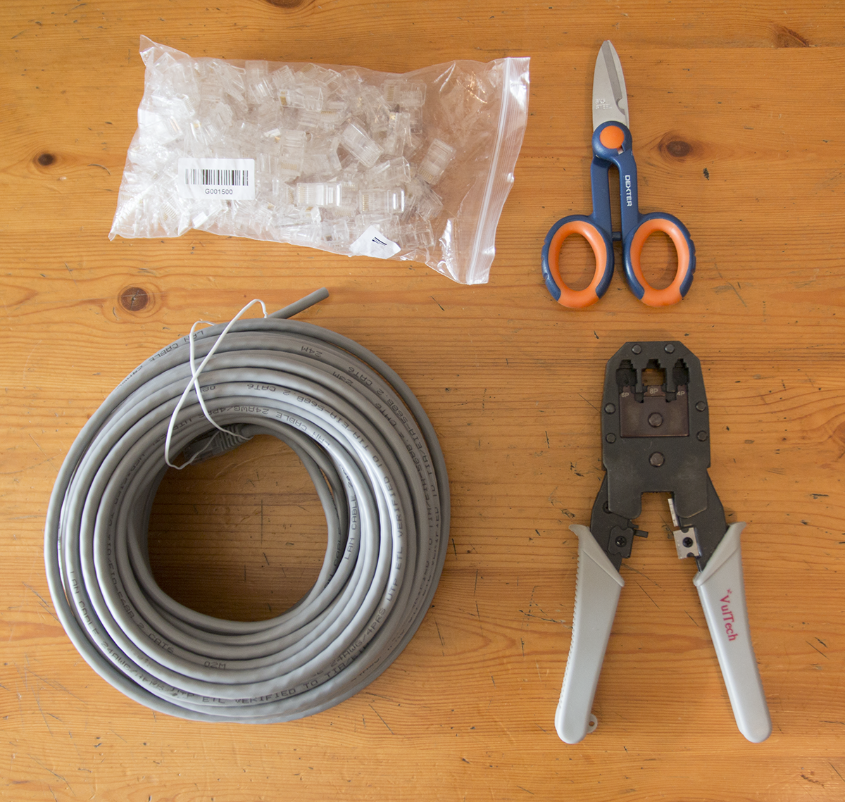
Now that you know what are the alternatives in the Ethernet world you are ready to purchase the right cable for your situation. But, what about setting it up? You will need to connect various devices together, some of them very close and some others quite far. The problem is that Ethernet cables ships only with some specific lengths: 1m, 3m, 10m, 30m, 50m, 100m. What if you need 70m, or 2, or 15..? The good news is that you don’t need to run a longer cable because the Ethernet cable is easy to cut and resize the length you want. Even if you work in networking remotely and cabling is not part of your tasks, knowing how to work with Ethernet cables is a mandatory skill that may turn useful when you are troubleshooting why data is lost somewhere in the network. To cut the cable, you just need a pair of scissors – any scissors will do. The hard part is not cutting the cable (you can cut it anywhere you like), but putting the termination at the end of it. The termination is just a plastic cap that takes the 8 inner wires and aligns them in a row so that they can “touch” the NIC on the device where the cable is going to be plugged in. You will have to ensure that all 8 wires are aligned and that they are in the right order: because devices expect a specific wire in a specific position and not in another and they are unable to work if you connected them wrongly. Before we can start resizing Ethernet cables, here’s a list of what you are going to need.
- An Ethernet cable of any category
- Scissors, possibly electrician scissors to remove the jackets
- Crimping tool (a specific tool used to “close” the connector onto the wire) – you can find that on Amazon.com for as cheap as 10$
- The “connector cap” itself, which is named RJ45 connectors (you will need at least two for cable, one per side)
Once we have all the equipment needed, the first thing to do is to define how long we want the cable to be. Then, once we found the point where we wish we have a connector, we just cut it. This step may seem trivial, and somehow it is, but it is important that you cut the cable perfectly straight as in the picture below. If you are not precise, the next steps will be harder if not impossible.
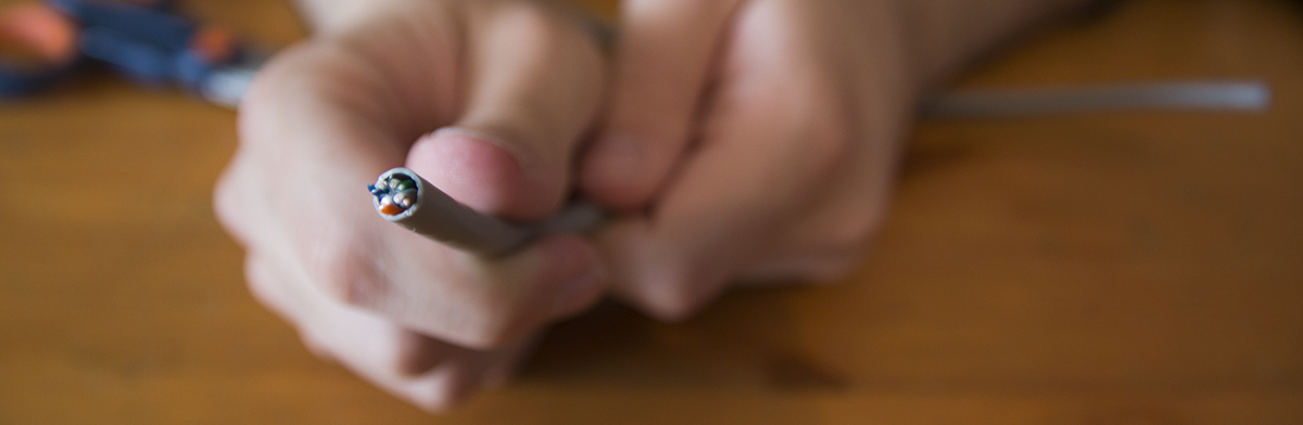
Now the cable is the size we want it, but this is just the beginning: we cannot put the connector on it yet. Instead, at this point, we are going to remove the outer jacket for about 0.5 inches or 1.5cm from the end of the cable. As a rule of thumb, you can use your thumb to have an idea of where to remove the jacket (see picture below). To remove the jacket, use the scissors without closing them tight, twist them at 45° and then pull toward the end of the cable. Exercise this step a bit, it may need some practice for you to find out the right strength you have to use in this process.
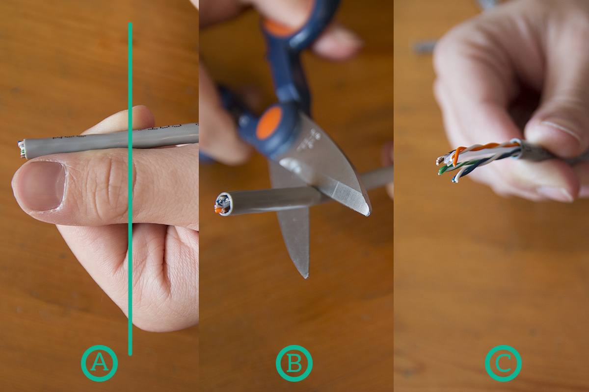
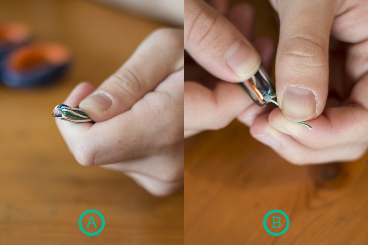
Once the outer jacket is removed, we need to ensure that outside the jacket we have only the eight inner wires. If you are working on a UTP cable you won’t find anything else, but if you are working with an STP cable you may find the inner spine (as in the picture) or the foils shielding the pairs. In any case, remove anything and remain only with the 8 wires.
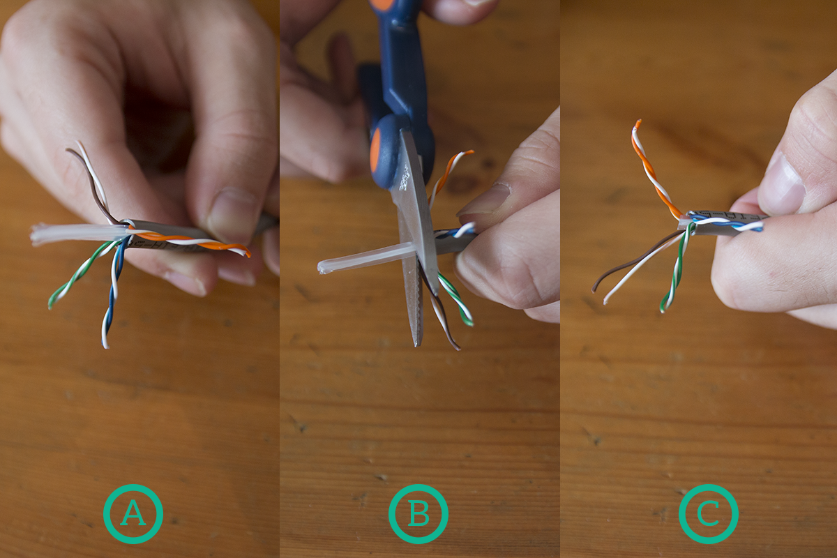
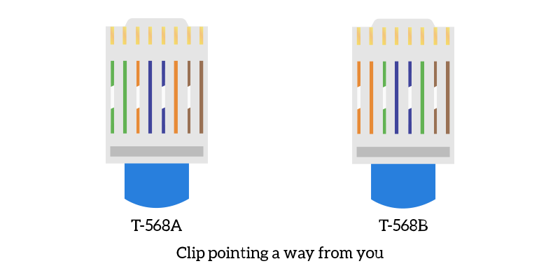
Now that we have the 8 wires we need ready to be put inside the connector, we need to know the order we have to put them in. There are two possible ways of creating a cable termination, named T568A and T568B. The only difference between them is that the orange pair in T568A is in the place of the green pair in T568B and vice versa. Take a moment to look at these color combinations, you will have to remember them. We will see later in this article what difference does it make if you use the first or the second termination.
Once you know the color combinations, the first thing you are going to do is to un-pair the wires. Just untwist the pairs and then try to make the inner wires as straight as possible. After that, bend all the wires backward and then take out of them the first color you wish to start with, such as white-green for T568A. Hold firm that wire and then align to it the next wire. In order to keep cables straight, help yourself with your thumb. Repeat the process until you place all the wires in the right order.
Now, we want to finally put the termination cap over those 8 wires, but we are just not ready for that. First, we need to ensure that the length of these wires outside the jacket is exactly the one we want. To do that, put a connector alongside the cable and remind that the hole on the bottom of the connector has to be on the jacket, as in the picture. Cut off everything else: while cutting the inner wires, cut them as straight as possible.
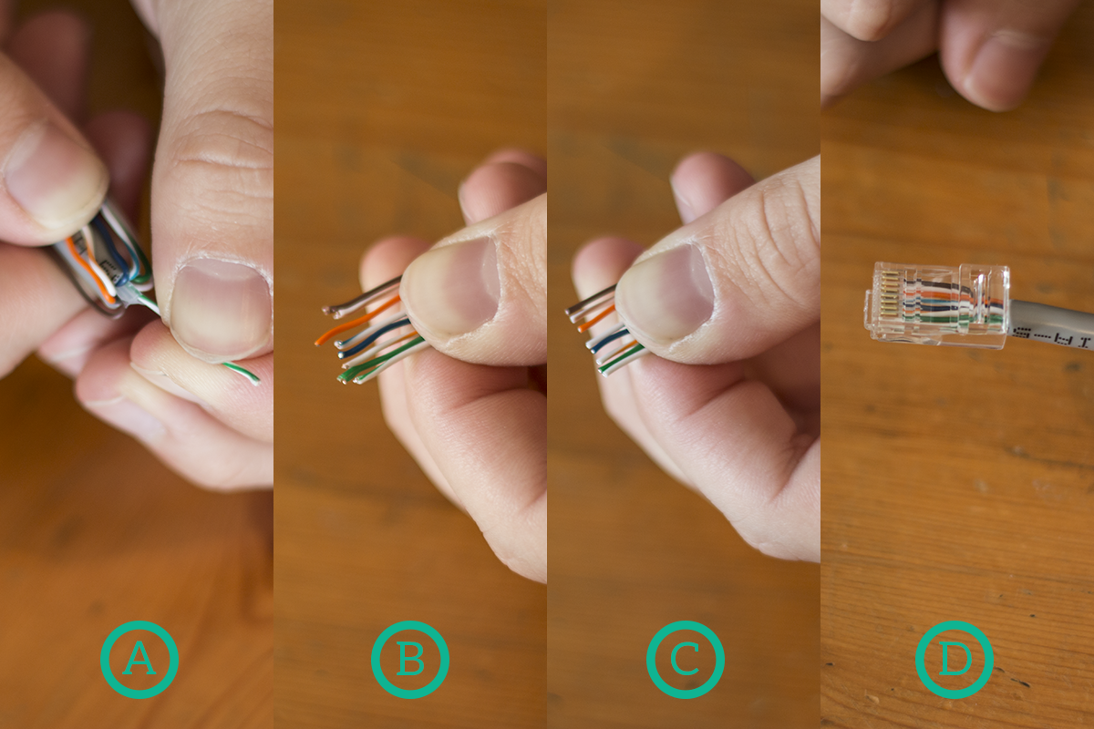
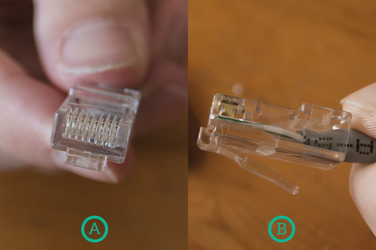
Now it’s time for the fun part: you just have to insert the wires into the connector. While doing so, always hold them firm with your thumb and, after you do that, ensure that they entered the connector in the right order. Remember, the color codes refer to the ones you’ll see in a connector with the clip on the bottom and the pins pointing toward you, so this is how we are going to insert the connector.
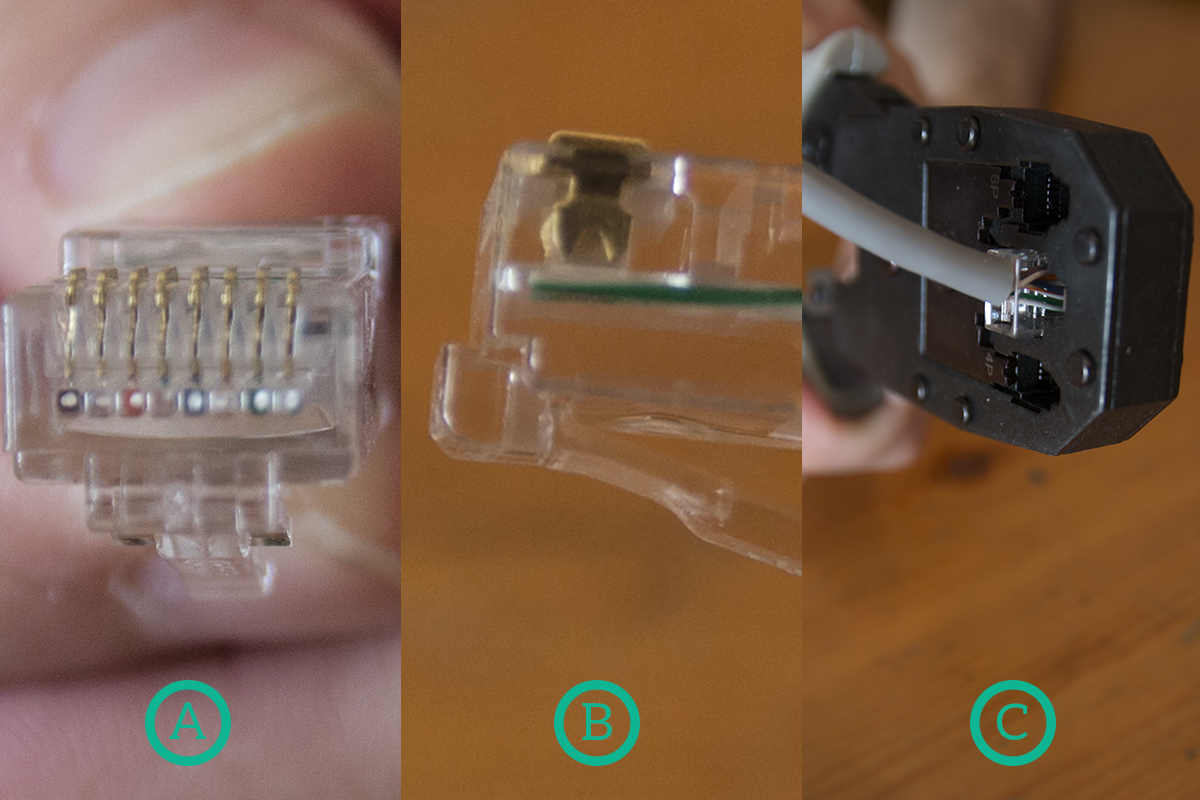
Ensure that you put the wires the deepest possible inside the connector, then double-check the color code inside the connector. If everything is right, then insert the RJ45 connector in the crimping tool, always holding it firm with your fingers. Then, close the crimping tool using a bit of strength in order to seal the RJ45 connector on the wire. Once you finished, ensure that all pins went down (as in the picture). What the crimping tool does is simply pushing down these pins onto the 8 wires and inserting in each of these 8 wires sort of a needle to connect the copper inside the wire to the device outside the connector, so the pins have to be all down.
Done! Now you have your connector ready. You just need to repeat the process on the other side and you will have a fully functional cable. If you find yourself creating ethernet cables very often, you may want to consider purchasing an Ethernet tester (Amazon.com, as cheap as 10$). An ethernet tester is a small electric device that you plug into an ethernet cable (actually, it is composed by two parts, one per side of the cable) and then it tells you if it has the right pinout (if cables are connected correctly) and, in some ethernet testers, it tells you if the cable is broken and, if so, after how many meters it is broken. It is certainly worth the expense if you work with cables every day.
Now, it’s time to consider the difference between T568A and T568B. The truth is, they are almost equivalent, but is the combination of the two that matters. If you have T568A on both sides of the cable, or T568B of both side of the cable, then you have a straight cable. This type of cable has to be used to connect devices of different types (PC with switch, switch with a router, and so on). Instead, if you have a T568A termination on one side and a T568B termination on the other side, you will have a crossover cable, used to connect devices of the same type (PC with PC, switch with switch, a router with a router). However, we must say that modern devices implement a technology called auto-mdix, that allows devices to talk independently from the cable connecting them.
Before moving on to the conclusion, another cable is worth mentioning. We are talking about the phone cable, which is terminated by an RJ11 connector. This type of cable was originally developed to bring telephone lines in houses, but then it was leveraged to deliver the Internet to individuals and small businesses. The ADSL technology is based just on that, a technology that allows you to receive more data per second than the one you can send (Asynchronous Digital Subscriber Line). This technology evolved over the years and allowed, with VDSL2, to reach a bandwidth of 30Mbps over a telephone wire. Not bad, considering that a telephone wire has 2-to-4 inner wires in it.
Delivering the Internet
This article was mainly focused on the Ethernet cable, and for a good reason. It is the cable for connecting users to the Internet. The last mile of the Internet, the one between you and your provider, is almost all Ethernet-based (or wireless-based). More than that, copper media in general were the ones that allowed the Internet to spread worldwide, changing the history of the world.
Maybe you won’t change the world with an ethernet cable, but knowing everything about it allows you to own your own local network (LAN) and do improvements on it. Once you know that, the next steps are fiber optic and wireless, then you will have a complete overview of what technologies allow the Internet to be not only delivered but also carried worldwide.

