
Any network engineer worth his salt can implement routing. In any Enterprise environment, static routes are simply not enough. They can’t scale and are slow to converge. Instead, Open Short Path First – or simply OSPF – is a great Enterprise-level solution. With it, you can build a dynamic routing infrastructure that can scale. Being an open standard, with convergence times and easy to implement (and scale) are all factors that make OSPF great for any environment, including yours. In this article, we are going to see all the theory behind it. We will explore the concepts of OSPF, and see how we can tune it. With this knowledge, you will then be able to implement it.
OSPF is a complex protocol, and we can talk about it for days. For this article, we will focus on the knowledge Cisco requires for the CCNA. Therefore, if you are a beginner, you will benefit from this article. It will give you a beginner-to-intermediate knowledge of OSPF.
Introducing OSPF
OSPF is a Link-State Routing (LSR) protocol. This means that, unlike RIP, it doesn’t exchange routes. When using OSPF, routers won’t tell each other “you can reach this subnet through me”. Instead, routers talk about links: they tell each other which other routers are their neighbors. For example, if Router 1 is connected to Router 2, it will tell: “Hey, I’ve a direct connection to R2”.
This process aims to give all routers an overall understanding of the topology. Each router must know the size and shape of the network. In a converged topology, all routers have a map of the entire network. Here’s a visualization of that.
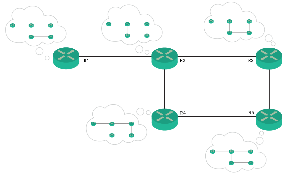
The map each router holds is the OSPF Database. However, once all routers have an updated database, we still don’t have routes. In fact, the router will take the database and look in it for the shortest path to any destination. Once found, it will add a route to the routing table. To do that, the router runs the Dijkstra’s Algorithm over the database. This can eat a lot of CPU, proportionally to the number of routers and subnets in the database.
In RIP, a router just tells its neighbor what are the subnets it can reach. With OSPF, each router knows the topology. By knowing it, it can autonomously select the best next-hop for each destination.
OSPF Adjacencies
How does communication happen?
Interestingly, OSPF implements its own transport layer. In fact, it doesn’t use TCP nor UDP, but directly IP. Router puts OSPF messages into IP packets and set the protocol number to 89. OSPF will have to handle acknowledgments and retransmissions on his own. OSPF uses unicast to send some packets, and multicast for some others. To increase efficiency, we don’t use broadcast. Instead, we use two multicast addresses.
224.0.0.5is the multicast address for All OSPF routers on the same network224.0.0.6is the multicast address for all Designated OSPF Routers on the same network. We will talk about Designated router later in the article
Generally speaking, all traffic that may interest multiple routers goes in multicast packets. Instead, specific exchanges between two routers will leverage unicast.
The Hello packet
Before two routers can start talking about links, they must form an adjacency. This simply means that two routers understand to be neighbors and to have the same OSPF parameters.
OSPF routers periodically send out Hello packets using the multicast address “All OSPF routers”. With these messages, that don’t need to be acknowledged, they tell they exist.
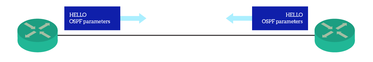
Routers put basic information about themselves in the hello packet. The purpose of that is just the discovery of new neighbors. Once two routers see (with hello packets) that are neighbors, they can start to create an adjacency. Only after that, they will start to exchange details about links. However, this process is not as simple as it might seem. Routers will go through multiple states, as we explain in the next section.
OSPF States
Introducing OSPF Router states
Two routers will need to go through 7-8 states in order to converge. Having a clear understanding of them allows you to troubleshoot OSPF issues. The 7 states you need to remember are: Down, Init, 2-Way, ExStart, Exchange, Loading, and Full. For the pros, we can add the Attempt state (right after Down).
The flow chart for these states is straightforward: each state can lead only to the next state. To that, we have just one exception if we need to consider the “Attempt” state. We consider that two routers have converged only when they reach the Full state. Remember that states aren’t just about routers. They indicate the state of a router toward another router. As a result, the same router can be in a state for the relationship with a second router, and in a different state for the relationship with a third router.
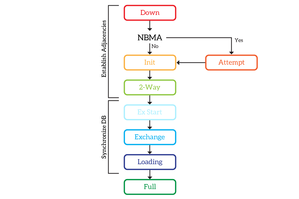
The states from Down to 2-Way have the major goal of forming an adjacency. Once that they form the adjacency, states from ExStart to Loading allow the two routers to talk about links. Once they agree on the topology, they move to the Full state that represents convergence.
Diving into OSPF states
To better understand how OSPF works, we need to look into its states.
- Down is the initial stage, the routers just don’t know about each other.
- For Non-Broadcast Multi-Access Networks, like Frame Relay, we have the Attempt state. It essentially means that the router is trying to establish a Layer 2 connection with the possible neighbor.
- In the Init state, the router has received a hello packet. Both routers must move to that state before continuing. This means that each router has seen the hello packet of the other.
- Once both routers have heard of each other, they move to the 2-Way state. In this state, they have established a bidirectional communication that can use to talk about links.
- ExStart indicates that routers are starting to exchange links’ information
- In the Exchange State, routers send each other a summary of their OSPF database. This allows the other routers to have an idea about the links the neighbor knows about
- With the Loading State, each router asks the neighbor for details about the new links. In fact, with the previous step, the router can tell what are the links that he doesn’t know (but that the neighbor does). With this step, the two routers will end up having the same OSPF database.
- The Full state indicates that the two routers have the same OSPF database. They are known to be fully adjacent.
In normal conditions, all routers should be fully adjacent. The only exception to that is where we need Designated Routers, as we will explain later.
The Router ID
To identify each link, we need to identify the two routers that form the link. To do that, we don’t use the hostname. We don’t even use the IP address, as each router can have multiple of them. We need something unique. To have that, we created a new concept specifically for OSPF: the Router ID.
The Router ID is a 32-bit numeric identifier of the router. We represent that in dotted notation (X.X.X.X), just like an IP address. However, remember that this is not an IP address. When you first configure OSPF on your router, it will try to create a Router ID on his own. To do that, it will look for the following items (in order of preference):
- The highest IP address among loopback interfaces (if any). If no loopback interfaces are configured, move to the next point
- The highest IP address among Ethernet (including Fast and Giga) interfaces
However, the best practice is to configure the router ID manually.
The OSPF Database
The Link State Database (LSDB)
We know from the introduction the routers hold a map of the topology. This is the OSPF database, technically known as Link State Database (LSDB). We call it LSDB because it simply contains all the links in the topology.
You can think about the LSDB like a set of tables. One of them stores all the links (Link States, LS – technically). Each Link State is a row containing the Router IDs of the two routers forming the links and a cost. The cost indicates how much does it cost to take this path (this link). Obviously, the lower the cost, the better. We will come back to that in a minute.
In the Exchange state, routers see a summary of the LSDB of the neighbor. That summary is known as Database Description (DBD), and it is a specific OSPF packet to be unicasted. Based on that, they decide which the Link States they need to know more information about.
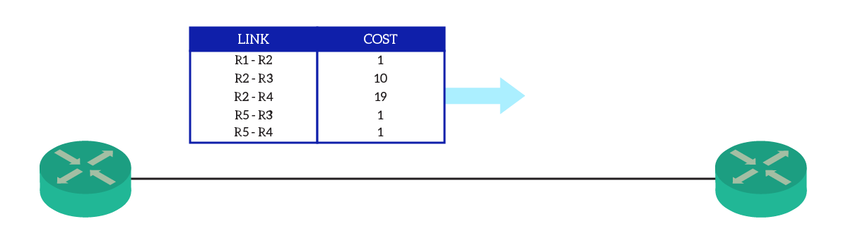
After that, they use the Loading state to retrieve such information. In that state, the router that doesn’t have a link ask for that with a Link State Request (LSR) message. The other router will reply with a Link State Advertisement (LSA) message. All of that happens using unicast.
Remember that OSPF is a master-slave protocol. When exchanging data, a router asks, and the other respond. They don’t do both things at the same time, but instead, they exchange roles once the first finishes.
Calculating the OSPF Cost
From the previous section, we know each link has a cost. This cost exclusively rely on the bandwidth of the link: the higher the bandwidth, the lower the cost. Specifically, OSPF has the concept of reference bandwidth. This is the bandwidth for which you want to have a cost of 1, and by default it is 100Mbps. Since the cost is an integer, if you have faster links (such as 1Gbps), they will still cost 1. However, Cisco allows you to change the reference bandwidth to fit your needs.
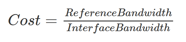
Calculating the cost of a link is simple, it is reference bandwidth over actual bandwidth. Calculating the cost of a path of multiple links (the metric) is also simple: it is the sum of the cost of all links in the path. When the OSPF produces two paths to the same destination, the one with the lower cost will go in the routing table.
It might be handy to know what is the cost of different bandwidths according to OSPF. The following table shows the cost each link has, based on different reference bandwidths (100Mbps, 1Gbps, and 10Gbps).
| Link | Speed | Reference 100Mbps | Reference 1Gbps | Reference 10Gbps |
|---|---|---|---|---|
| Ten Gigabit Ethernet | 10Gbps | 1 | 1 | 1 |
| Gigabit Ethernet | 1Gbps | 1 | 1 | 10 |
| FastEthernet | 100Mbps | 1 | 10 | 100 |
| T3 | 45Mbps | 2 | 22 | 223 |
| Token Ring | 16Mbps | 6 | 63 | 625 |
| Ethernet | 10Mbps | 10 | 100 | 1000 |
| E1 | 2.048Mbps | 49 | 488 | 4883 |
| T1 | 1.544Mbps | 65 | 648 | 6477 |
| 64kbps line | 64Kbps | 1562 | 15625 | 156250 |
| 56kbps line | 56Kbps | 1785 | 17857 | 178571 |
| 9.6kbps line | 9.6Kbps | 10416 | 104167 | 1041667 |
With this knowledge in mind, we are now ready to dive into two OSPF-specific topics.
The good part of OSPF
Designated Router, Backup Designated Router
OSPF adjacencies are peer-to-peer. It means an adjacency involves two routers, and only two. Imagine we have a switch, and we connect three routers to it. If they were to talk OSPF, they will need to establish adjacencies between each other. So, R1 will have an adjacency with R2 and another with R3, and R3 will have an adjacency with R2 as well. This results in having 3 adjacencies, which is acceptable. If we add another router, we have 6 adjacencies. If we have 10 routers, we would have 45 adjacencies! This is way not scalable.
To overcome that, OSPF engineers invented the concept of Designated Router (DR), and its backup (BDR). On a broadcast network, like Ethernet, OSPF routers will elect a designated router and a backup. Then, they will establish adjacencies only toward them. The DR will make updates from a neighbor, and sync the others. The BDR maintains the adjacencies already up to replace the DR in case it fails. If the DR fails, the BDR becomes the DR, and a new BDR is elected.
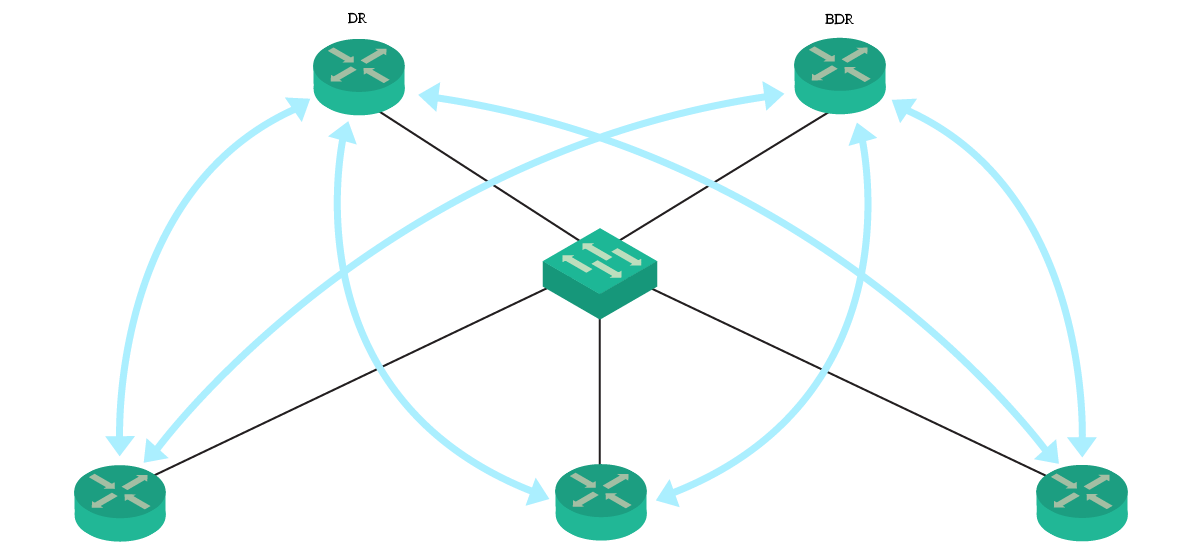
To elect the DR, we need to look at a specific field: the priority. This is an administratively chosen value, designed for the DR election, which is included in all Hello packets. The router with the highest priority will become the DR, while the router with the second-highest priority will become the BDR. In case of ties on the priority, we consider the Router ID (the higher the most likely to become DR). Furthermore, if we manually set the priority to zero, that router will never be a DR.
OSPF Areas
For the whole article, we haven’t mentioned the concept of area. Believe it or not, this is a key concept for OSPF, but Cisco doesn’t require you to leverage it at the CCNA level.
The more routers you add to the OSPF topology, the more processing the LSDB becomes CPU-intensive. Because of that, you generally shouldn’t have more than 50 routers in the topology. However, many networks will have many more of them, but this doesn’t mean we can’t use OSPF.
You can group routers into areas, groups of contiguous routers. Then, routers will use their LSDB to map the topology only of routers in the same area. For routers in a different area, they don’t care anymore about the status of links. Instead, they care about routes, just like with RIP. Some router known as Area Border Routers (ABR) will have an interface in an area, and another interface in another. ABRs will take the LSDB from an area, and create inter-area routes to inject in the other area. Of course, this is true from both directions.
Grouping routers into areas bring many benefits. In fact, this isn’t simply a way to save CPU resources:
- Allows segmentation of the network
- Creates summarization points (the ABRs), potentially reducing the size of the routing table
- Reduces convergence times and management traffic (inter-area updates)
In fact, with area, if a link goes down only routers in the same area will be notified. Other areas will be notified only if there is a change in routes.
The Backbone Area
OSPF identifies each area with a numeric ID. On top of that, it defines the concept of the backbone area, an area with the role of connecting other areas. The backbone area must have the ID set to 0. As a requirement, all areas must have at least an ABR shared with area 0, making them directly connected to area 0. In CCNP, we learn how to circumvent that, but this is not recommended. By design, use area 0 at the center of your network.
As a result, your topology will look something like this.
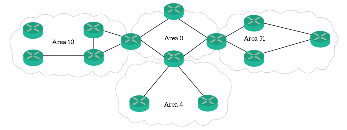
Tip: for the CCNA, you are going to use OSPF single-area. This means you will configure all routers in the same area. If you do so, you must use area 0. An OSPF topology where no area 0 exists is simply a bad design. Remember that for the labs and for the exam too!
Conclusion
In this article, we discovered what is OSPF and how we can use it. With this knowledge, you are now able to understand a complex routing environment that leverages this protocol. To do that, there are some concepts you absolutely need to remember. Here’s a quick recap:
- OSPF is a Link-State protocol, it propagates changes to links to other routers. It identifies each router with a Router ID (32-bit)
- Updates are forwarded “as they are” by the neighboring router because the goal is to make all router know the entire topology
- Routers maintain a representation of the interconnection in the networks, the Link State Database (LSDB)
- In a broadcast (or generic multi-access) network, routers elect a Designated Router to coordinate updates. As a result, we limit redundant updates on that segment
- OSPF groups router into areas: all remote areas must be connected to the backbone area (ID 0)
- Routers that are in at least two areas are known as Area Border Routers (ABRs)
Take a moment to truly understand these concepts, and read again the article if necessary. In the next article, you will try your knowledge by learning how to configure a full OSPF topology.


2 Responses
Hello!
Firstly, you made a wonderful course here, I am here to refresh my memory before getting mu certification. I already recommended it to all my colleagues 😀
Secondly I wanted to mention that OSPF multiarea is CCNa topic: https://learningcontent.cisco.com/cln_storage/text/cln/marketing/exam-topics/200-125-ccna-v3.pdf
“Configure, verify,and troubleshoot single area and multiarea OSPFv2 for IPv4 (excluding auhentication, filtering, manual summarization, redistribution, stub, virtual link, and LSAs)
Configure, verify,and troubleshoot single area and multiarea OSPFv3 for IPv6 (excluding authentication, filtering, manual summarization, redistribution, stub, virtual link, and LSAs)*
This is just an FYI 😀
Keep the good work otherwise!
Hey! Thank you so much for your compliments and your support! 🙂
I’ll update the guide ASAP regarding OSPF multiarea, I am happy you mentioned that!
Comments are closed.