
Connecting devices is not simply running cables from a device to another, you have to know what you are doing. All the devices in a network and the way they are connected together form the network topology, the topic of this article. We will learn what are the possible network topologies out there, what is their difference and how changing from a topology to another can completely modify the way our network works. With that knowledge, you will be ready to climb the OSI stack easily.
Network topology at a glance
Network topologies can be defined as the map of a network, but the formal definition is the following.
A network topology is the representation of links between the nodes within a network.
This can feel somehow too formal, at a first glance, and probably it is, but once we clarified the concept of node and link you will truly understand this definition. A node is any device that can be plugged into a network: it does not matter how it can be plugged in (with a cable, in Wi-Fi and so on), but as long as it is capable of communicating with the rest of the network it is considered a node. A Desktop computer is a node, but also a router, a smartphone, a laptop, or a switch. Even smart-home devices such as connected-fridges or lamps are considered nodes if they can talk over a network.
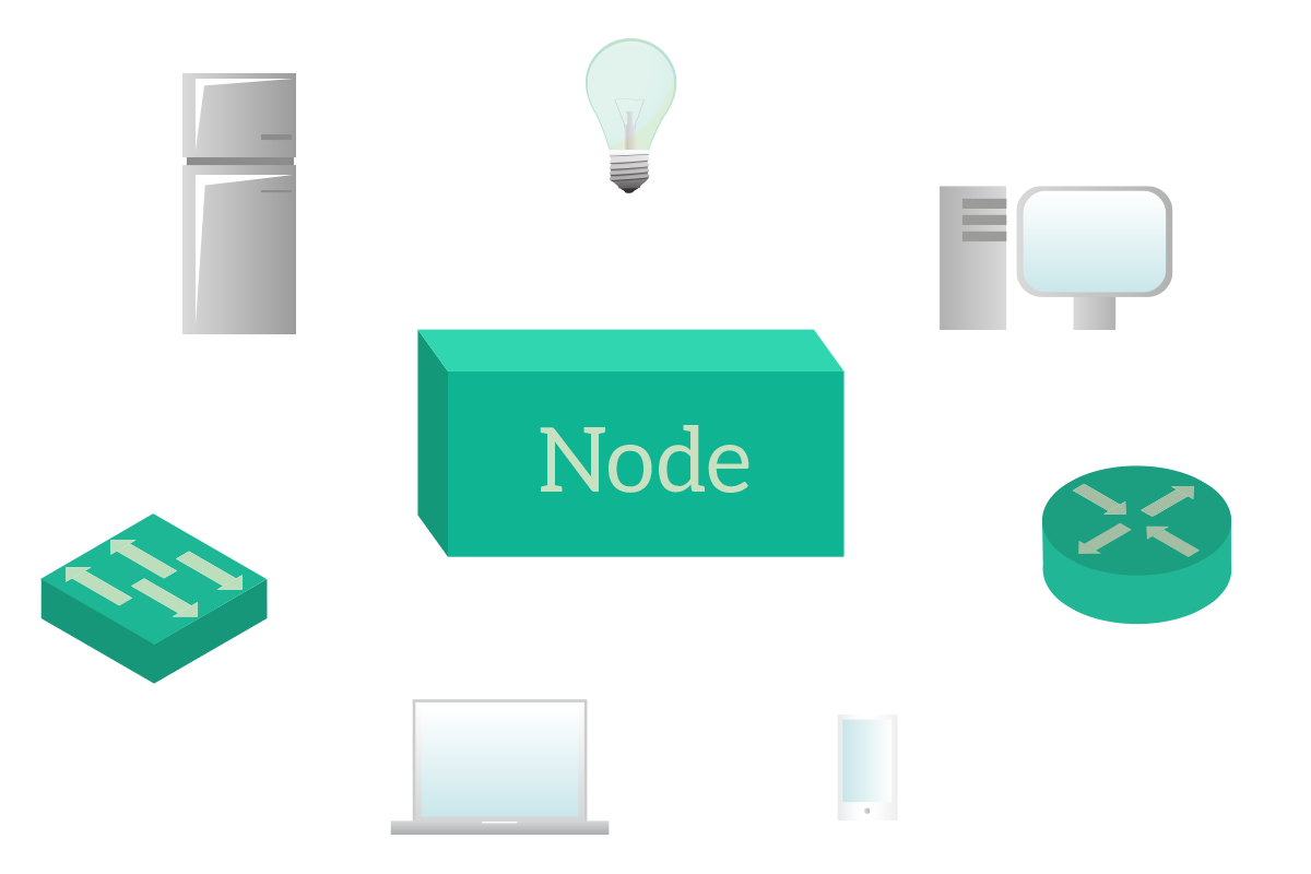
The node is any device. The link, instead, is any type of connection that can allow two devices to talk. A coaxial cable is considered a link, but also an ethernet cable or a fiber optic cable. Even a wireless connection is considered a link. So, to be short, a node is any device, a link is any connection. The topology is the combination of both, it is a drawing where links (drawn as lines) connect nodes together. The way this connection happens can change a lot of things.
The first thing that is influenced by the network topology is the path that your data will have to travel when going from a device to another. Even if it looks trivial to you, take a moment to think about it. There are a lot of things involved, going far beyond the simple delivery of the information to the other node. For example, if we force traffic in a certain predictable path, we can do something in that path to filter or analyze traffic (blocking malicious sites, limiting access to social networks during business hours…). To do that, we must know the network topology. Take a look at the following two cases, they are very important to have a general understanding of how networking works.
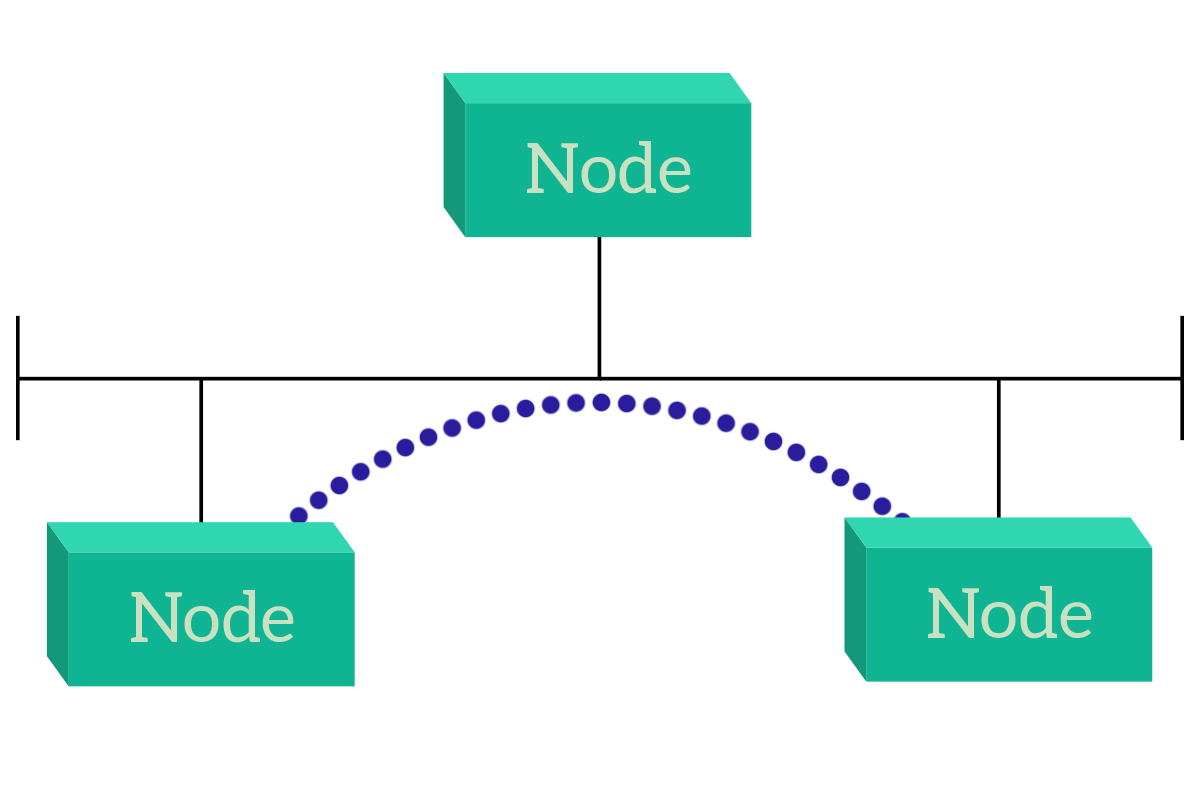
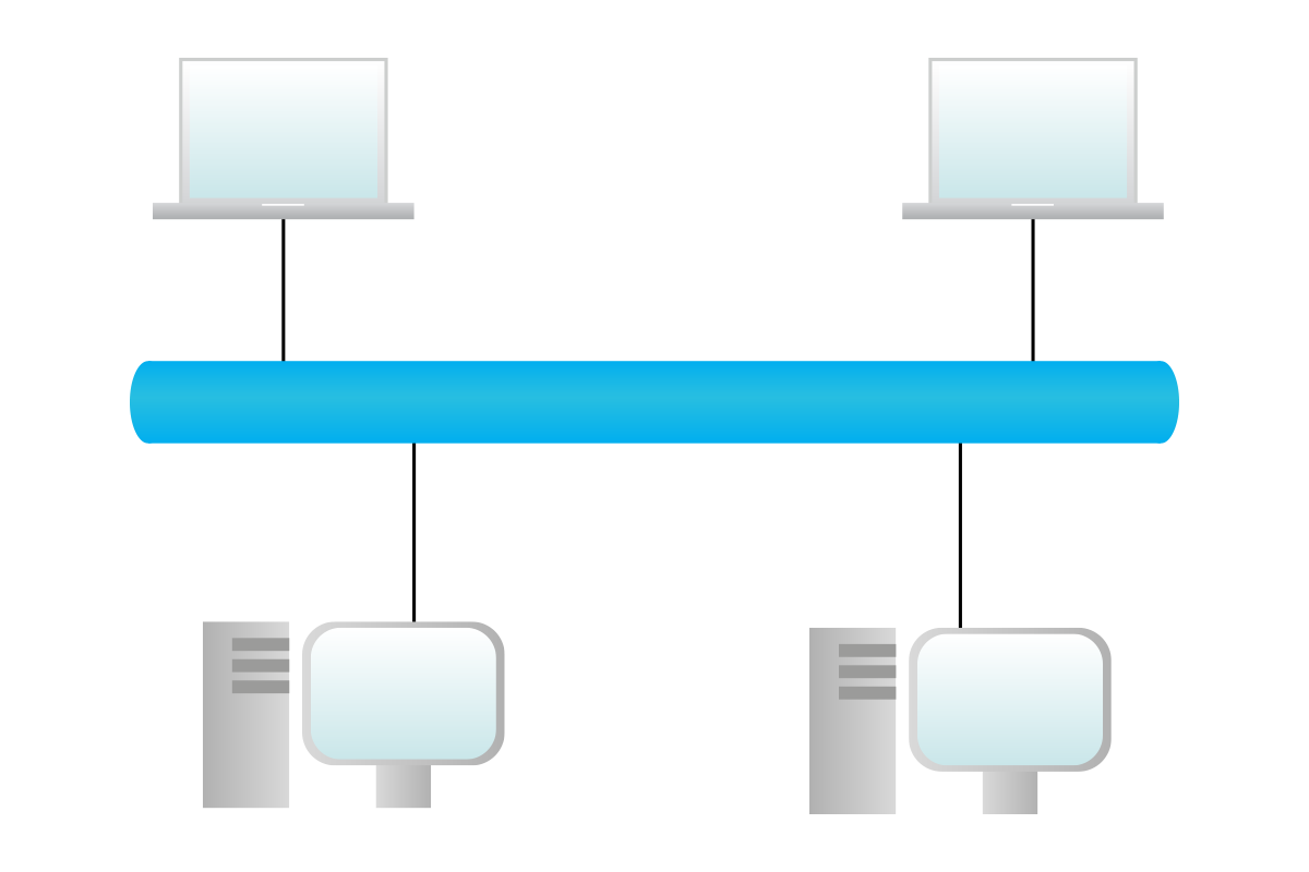
In the first case, the nodes can talk directly to each other. The reason for that is that they are connected all on the same link, and this is a general rule: nodes on the same link can talk to each other directly. This is known as direct access, and there’s a specific topology for that, known as a bus: in a bus topology, all nodes are connected to the same link.
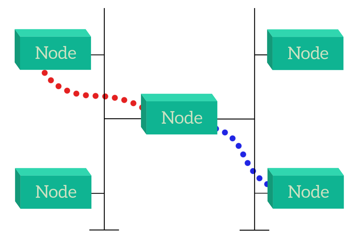
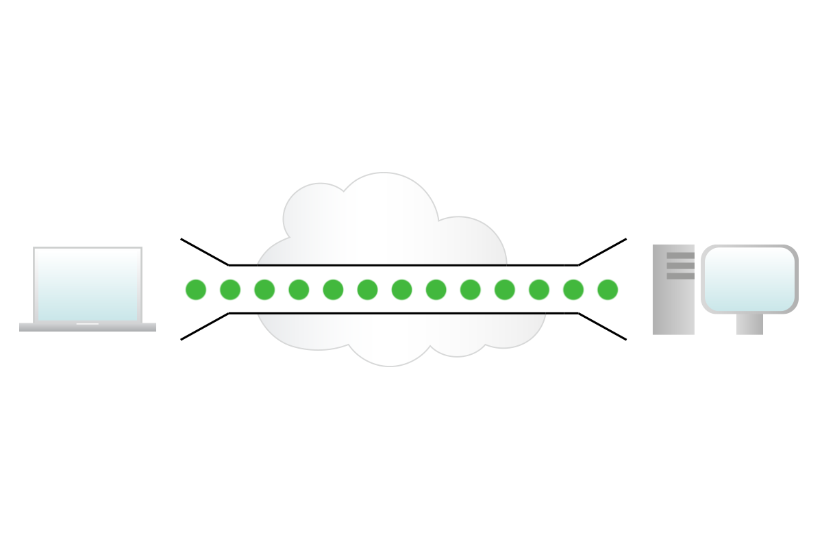
This solution has some drawbacks that we will see when talking specifically about the bus topology, but the point is that devices can talk directly with their destination. Instead, if devices do not share the communication media (link), they can still talk to each other, but traffic has to pass through another device (or more!). This is not an issue, but it is something to be considered. For example, that device can be our appliance intended to do traffic filtering (a firewall or an inline-proxy) or can be a device that is just intended to forward information on behalf of other devices (a router or switch), in this case, it is known as an intermediary device.
With these two examples, it is easier to understand how the way devices are connected together changes the way they interoperate. This is the key reason that makes the study of network topologies so important. In the following sections, we will continue to talk about the bus topology, or shared media, to move to the star and hierarchical topologies, finally ending up with meshes.
Shared media
In a shared media topology, nodes are connected together by the same link or media. Today, that link is going to be the air for wireless connections, but in the past, it used to be a special implementation of a coaxial cable to connect multiple devices. The symbol of a shared media (a cable terminated on both ends) comes from that coaxial cable, which needed specific terminations on the ends to absorb the signal, otherwise, it would have been reflected back into the cable creating interferences (that’s why the T-shape).
The first thing we notice is that the design is extremely simple. It’s just a cable! Furthermore, everything a device “says” on the cable is heard from all other nodes, so it’s easy to communicate. However, this causes a problem: communication cannot overlap, so if a node is talking no other node should be talking. In other words, only a single device can be talking at a given time, and this dramatically reduces scalability because the more devices in the network, the more you will have to wait. However, we have no alternative but to share air between devices when it comes to wireless, so if this problem cannot be solved (as in the Wi-Fi case), we should try to find some techniques to mitigate it.
These techniques have been developed in the form of algorithms, programs that run on each node, and that control how it can interact with the device. Two major algorithm branches have been developed over the years, Carrier Sense Multiple Access (CSMA) and Token Ring. With CSMA, devices listen to what is happening on the shared media and decide if they can talk, based on that. With a token ring, a virtual token is passed between devices, and only the device with the token is allowed to talk. Let’s have a complete overview of these techniques.
The CSMA branch is the algorithm branch that we use today, the true leader of the scene. This is because it is the one maximizing the throughput for that shared media. This is possible because devices decide autonomously if they have to talk or not, and the devices that have something to say can talk almost immediately. CSMA comes in two flavors, Collision Detection (CSMA/CD), and Collision Avoidance (CSMA/CA). The “Avoidance” version is a little more sophisticated, and it is the one used for wireless transmission. For now, we will focus on the most basic one, the Collision Detection algorithm. The logic behind this algorithm is extremely simple, as in the picture: listen for that is happening on the media and talk as soon as nobody else is talking.
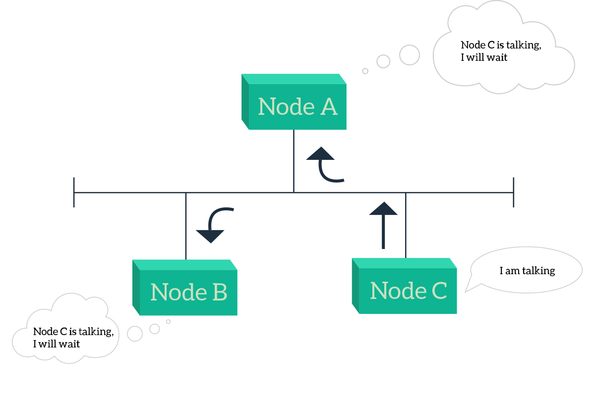
The situation in the picture is simple: both Node A and Node B want to talk, but Node C is already talking so they will have to wait. The real problem happens when node C stops talking, both A and B will start to talk simultaneously, causing signals to overlap and, in the end, disrupting the communication. So, something else has to be put in place to address that specific issue. Once nobody else is talking (the shared media is idle), the node waits silently a 96-bit time, the time needed to transmit 96 bit of information. Then, if the channel is still idle, it starts to send the signal. While sending the information, the node continues to monitor the media and assume that the delivery was successful only if it does not hear anything else while it is sending the information. If instead, it detects a collision, it stops transmitting immediately and send a 48-bit special signal (the jamming signal) to notify other nodes that a collision just happened. If the transmission went bad, and a collision was detected, the transmitting nodes that have detected the collision waits a random amount of time before they start the process again. This has to be random in order to avoid that the two stations will try to overlap each other exactly the same way the next time, with a random timer a minimum delay can be created to prevent just that: this process is handled by the back-off algorithm. If you are a programmer, you would find interesting the pseudo-code for CSMA/CD presented below.
while ( true )
  if ( hasSomethingToTransmit() )
    while ( mediaIsBusy() ) ;
    wait(96bit_time);
    if ( mediaIsIdle() )
      transmit()
      while ( transmitting() )
        if ( collision() )
           jamSignal()
           wait( random() )
With CSMA/CD, if the media is idle, any device that wants to can transmit. This maximizes the usage of the media, providing the best throughput to the connected nodes. However, there is also a legacy technology that was used to allow nodes to talk over shared media. It’s named Token Ring, and it was developed originally for circular topologies, where each node is connected to the previous one and the next one, and the final node is connected to the first, creating a closed ring. The logic behind that is that it is very simple, nodes elect a “master” node that generates a token, then that node sends the token to the next node and, if it has something to transmit, sends that too. The information in this process can be compared to a train, where the token is always the first wagon or the locomotive, and the information is the second wagon. The next node will scan the information wagons and if it finds one or more wagons that are destined for itself, it will take them off the train. Then, it will attach what it has to send and push the information train to the next node, and so on. To put that very simple, with this technology only the node currently having the token can talk. If this was originally deployed for rings, it can also be applied to shared media, with the advantage that there is no need to do fancy stuff with trains and wagon because when a node is taking, all the nodes will be listening immediately.
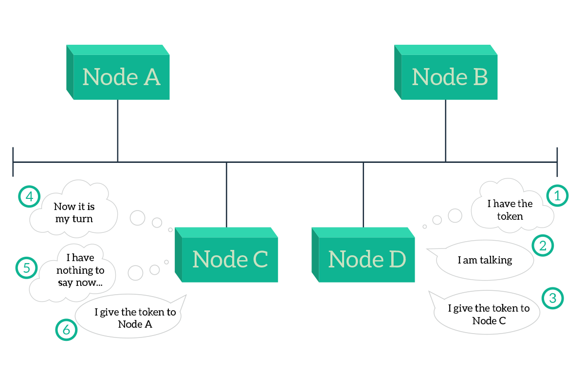
As the picture highlights, if a node has nothing to say, it always has to pass the token to its next node. This approach cannot optimize the usage of the media, because the grants to talk are distributed equally, so that if a node has much more information to send while the others have nothing to say, then the node with more information will have to wait, while the other will obtain the token with no need, wasting time and throughput. Due to the lack of flexibility of this technology, the token ring is no longer used, even if some pieces of hardware still support it.
In both approaches, CSMA/CD and Token Ring, a single device can talk at a time: when that device is talking, all the others have to listen and cannot talk. However, later on, the device that was originally talking will be listening, while another device will be the one doing the talk. This type of transmission has a name, half-duplex. This, alongside simplex and full-duplex, is a type of transmission, as the following list explains.
- Simplex – information can flow in a single direction (such as “From A to B, but not from B to A”)
- Half-duplex – information can flow in both directions, but not simultaneously
- Full-duplex – information can flow in both directions simultaneously
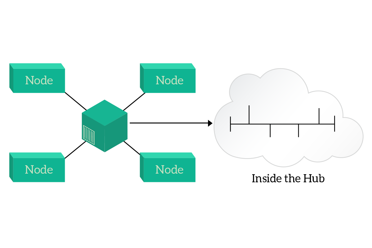
It’s easy to guess: the best one is full-duplex. Fortunately, modern networks are completely full-duplex, but getting to that point in technical deployment was not so easy. Originally, the shared media was a coaxial cable running on the wall of an office, with computers plugging onto that cable. The next step was to concentrate that shared media with the hub. A hub is a legacy device where all the computers can connect into, and that has inside nothing more than a shared media. The improvement is, however, that hubs work with ethernet cables (RJ45) and that this way you centralize the point where computers connect to the rest of the network. Instead of having a cable running for all the offices, you have one cable per computer, going from the computer to the hub. This way, a fault on a cable will disconnect just a single computer and if the hub fails it will be replaced easily (you don’t have to remove all the cable run).
With the hub, you improved some physical characteristics of the network, but you still have half-duplex communication. The evolution of the hub is the switch, and it is able to support full-duplex transmission between any pair of connected nodes. This device will be explained in the article dedicated to the data-link layer, for now just know that the switch is the way to go in order to have a full-duplex transmission. Now, instead, it is time to face some other topologies available in a network deployment.
Star and Hierarchical
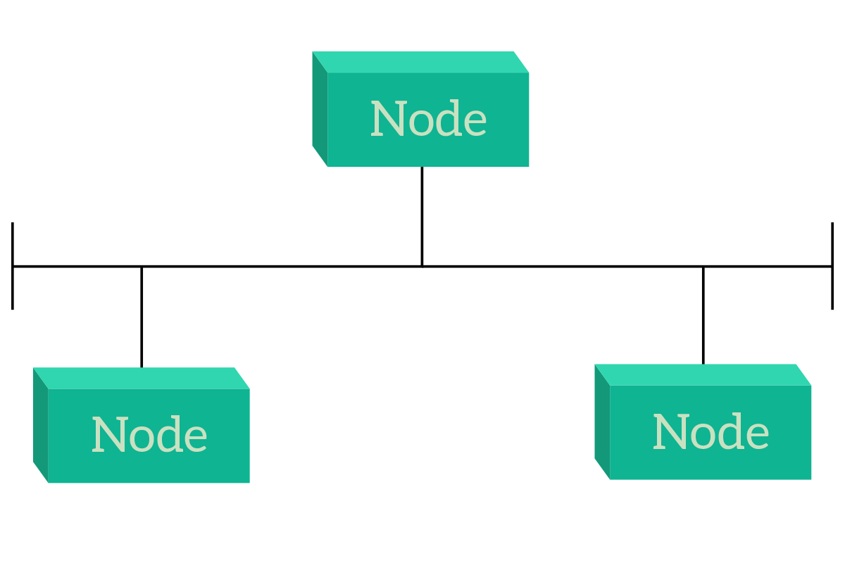
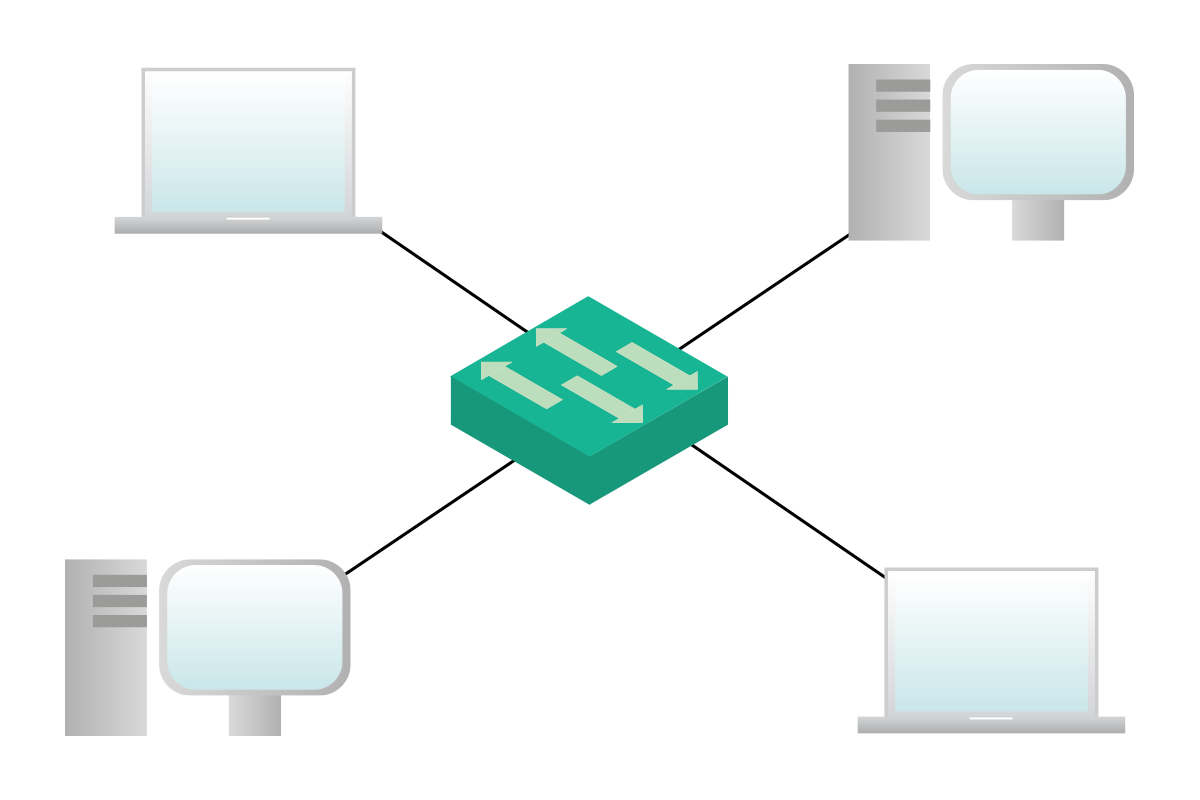
Now it’s time to talk about the most popular topologies in Campus networks (as a reminder, the campus network is the one that serves user devices such as laptops and smartphones). But these two topologies, star and hierarchical are the best practice to be used also in data centers (connecting servers). In other words, at the moment they are the best choice in most cases. Let’s start with the star, which is fairly simple: all devices connect to a single device in the center.
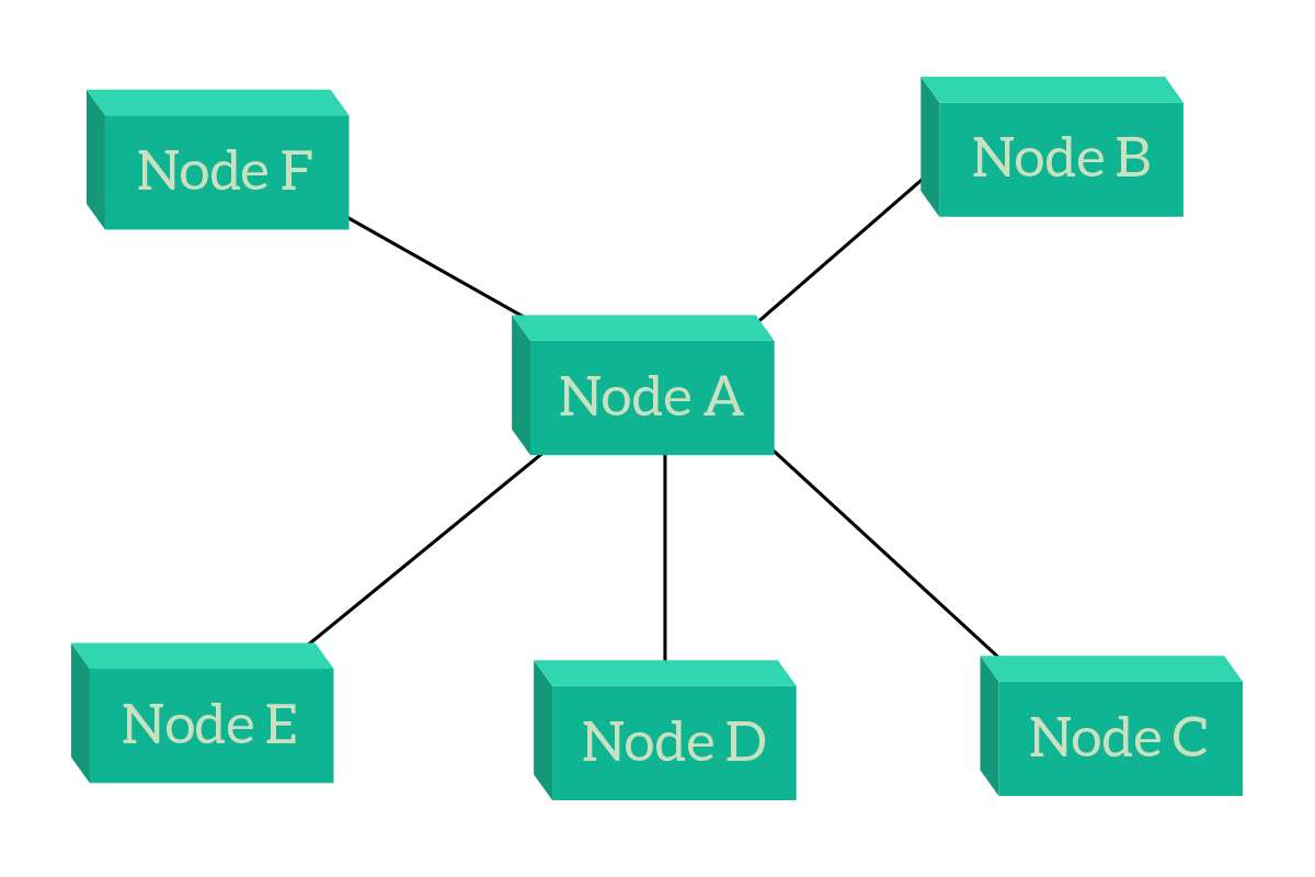
The major benefit of a star topology is related to centralized management and control. Since all the traffic passes through Node A, we can apply a policy to restrict some users to reach some other devices on the network, we can filter and inspect traffic to allow or deny some specific applications, and we can manage the overall infrastructure from the central point. If we were to attach Internet to this topology, we would most likely attach it on Node A. This way we put it in the position which is equally reachable from all nodes (all nodes have to traverse a link and then are on Node A, and therefore on the Internet – on any other node, anyone but that node would need to traverse two links). The problem with that design is that if Node A fails, all the other nodes will be disconnected and isolated. This can be resolved by adding two central nodes that work equally, but this is a technology we are not ready to face just yet. Working with that topology, remember that external nodes are generally end devices (computers, servers, etc.), while the central node is an intermediary device (hub, switch, router, etc.).
The evolution of the star topology is the hierarchical topology, which is a star of stars. Actually, the star topology is a hierarchical topology itself, because – by definition – a hierarchical topology is a topology where traffic flows between leaf nodes by passing through one or more central nodes. The picture will give you a better idea of that.
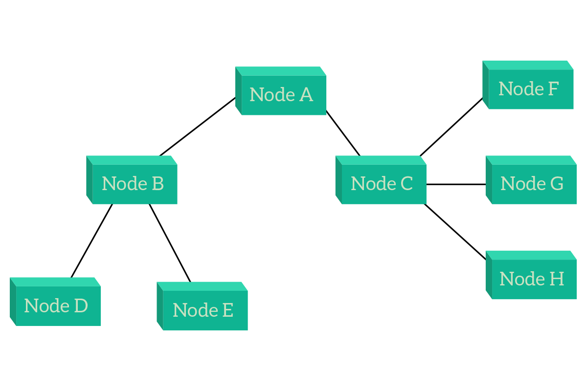
As you can see from the picture, this type of topology highly resembles an upside-down tree. And this is so true that external nodes are called leaf nodes: nodes that have only a single connection. Leaf nodes are connected to a node, which then is the leaf of another node, which then is the leaf of another node and this way up to the central node, known as root. This is the most used topology because it is flexible and scalable. In order to talk with each other, traffic between nodes has to flow up to the first central node the two leaf nodes have in common and then go back down to the destination. As an example, in the previous picture, traffic from D to E will go to B, while traffic from D to H will go to B, then to A, then to C and finally to H. To better explain the topology, nodes have been categorized in layers. Leaf nodes, end devices, occupies the lower layers, which can be assumed to be layer zero. Then, the first intermediary devices we encounter (B and C in this case) are layer one, while A is layer two. There can be also a third layer if there are more devices, but be aware that these layers have nothing to do with OSI layers. They are not related at all.
As an advantage of this topology, we still have centralized management and control. In this topology, if any node which is not a leaf (layer one or more) fails, other devices will disconnect but this won’t disrupt the whole topology, it would be segmented (divided) instead. This is true even if the root node fails. Now, nodes do not have infinite ports to plug cables in, so you cannot connect infinite devices to the same central device, so a multi-layer hierarchical topology is much more scalable (that can be expanded in the future) than a star topology, which can be considered a mono-layer hierarchical topology. Even there we can create a pair of central devices to maintain the normal functionalities even when a central device fails. For these reasons, this topology is certainly the best choice.
Meshes
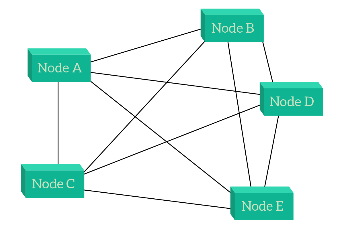
At first glance, meshes seem random topologies. And if you don’t know the reasons behind them, they actually are random to you. A mesh is a topology where a node is connected to one or more other nodes, in such a way that at least one path exists between any two given nodes. Two types of meshes exist, the full mesh and the partial mesh. In the full mesh, every single node is connected to all the other nodes in the topology. This adds reliability to the network because even if one, two or even more links or nodes fail within the network, other nodes will still have a way to talk. However, this setup is extremely expensive and hard to manage (each time you add a node you will have to connect all other nodes).
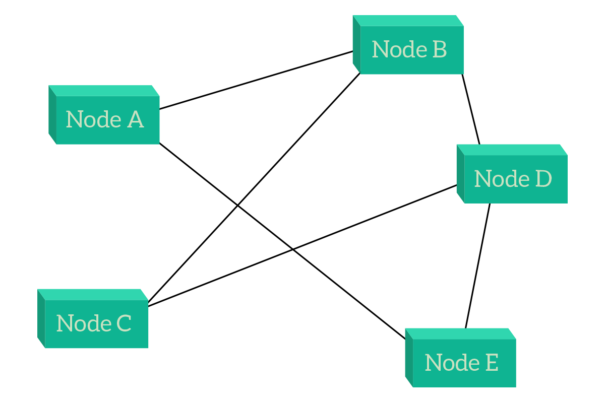
Something that looks somehow like a compromise is the partial mesh, where each node is connected to multiple nodes, but not necessarily to all the others (unlike the full mesh). Generally speaking, crucial devices will be the ones having more links so that they can be connected even after link failures.
Meshes (full when it is possible, otherwise partial) are mainly used in the Service Provider environment, to interconnect sites distant miles. Connections between cities and countries are mainly partial meshes, but this is not limited to the network within the service provider. Instead, this is also true for the connection between two different service providers: if you look at all the provider’s network together and imagine that each network of every provider is a single node, you will see a partial mesh. The benefits of meshes include the use of a direct path (use a single link) when available while using a path with multiple links when a direct one is not available (such as in partial meshes). The major drawback, instead, is the higher cost: think about how much would it cost to run one more submarine cable between London and New York.
Layer 2 and Layer 3 topologies
OSI layers and network topologies are related topics, and in this section, we are going to explain why. The OSI layers define at which level we are going to work: the first layer is for the people working with physical components like hardware and cables, while the seventh layer is for people working with applications. In other words, OSI layers define the level of detail of the network. The lower the level, the higher the details (but the smaller the picture), the higher the level, the less the details (but the bigger the picture).
Now, think about network topologies in a different way. Think that links are divided from each other by devices. Depending on the level of the topology, you will have some devices included implicitly within a link. In other words, when in a topology you represent a link, it does not necessarily mean that it is just a cable or a wireless network, it could be also a set of cables and devices. The following paragraphs explain that in detail; they are followed by a network topology. The network represented is always the same, but the level of details changes in each topology.
In a Layer 2 topology, each device working at the OSI Layer 2 (Data Link) and above has to be represented. Basically, any device has to be represented in this type of topology, except repeaters and converters. This topology is used to display how devices are physically connected with each other.
In a Layer 3 topology, each device working at the OSI Layer 3 (Network) and above has to be represented: these devices are routers, firewalls, computers, and so on. Switches, bridges, and hubs are not represented but instead included implicitly within links. As you can imagine, the network layer is the most important one since we are network engineers, and this type of topology is the one used to have a logical overview of the network and to understand the path that information has to go through in order to traverse the network.
At the OSI Layer 4 (Transport) and above, we don’t have topologies anymore. This is because these layers just do not care about the underlying network and path, so we just represent tunnels: logical connections between devices and/or applications. These types of drawings are used specifically for security purposes to represent which type of traffic has to be allowed and which type of traffic should be blocked instead.
With this article, we discovered the topologies in networking. These concepts are crucial to have a great understanding of how things work in an ICT environment. Having a map of the network – the topology – makes everything easier, because we know how to get around, we know what’s going on. With that in mind, we are ready to face the fundamentals layers from the OSI stack, data link, and network. But that is for another article.

