VLANs are a simple yet effective way to keep traffic separated (need a refresh? check our article about VLANs). However, without something else, VLANs will keep traffic completely isolated. By default, in fact, devices in a VLAN cannot talk with devices inside a different VLAN. This is far from the desired behavior. Our goal is to allow traffic between VLANs via a trusted device, acting as an intermediary. In this article, that device is a router, as we are learning Inter-VLAN Routing with Router on a Stick (RoaS).
This article explains to you how to configure Inter-VLAN Routing with RoaS, therefore it comes with a lab. You can download this configuration lab from the link below, then open it with your Cisco Packet Tracer.

As soon as you downloaded it, open it, and continue with the reading. You will benefit the most by trying the lab as we proceed with the configuration.
Inter-VLAN Routing with RoaS Lab Intro
The Topology
For this lab, we are going to use a simple topology with three switches and one router. We use this environment to serve 10 computers, spanned in three different VLANs.
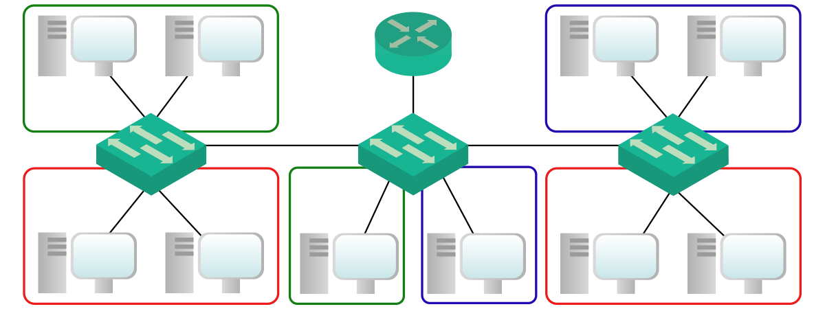
In case it wasn’t clear, the only router in the picture is the one we will use for Inter-VLAN routing. Therefore, all traffic that has to go from a VLAN to another, will flow through this router. If you open the Packet Tracer, you’ll see we called this device just “RoaS”.
The Requirements
This lab comes almost blank. We already configured for you all 10 PCs with IP address, subnet mask, and default gateway. However, all network devices are with factory configuration (we just changed the hostname). Consequently, you will need to configure the VLAN part, including trunks, and the Inter-VLAN routing part. To be more specific, here’s what we need to do.
- Create three different VLANs with IDs 10, 20 and 35, named respectively “Red”, “Blue” and “Green”
- Configure access ports and trunks according to the tables below
- Configure “RoaS” Router to do Inter-VLAN Routing for the three VLANs previously created
Before we start the configuration, we will present to you the logic of Inter-VLAN routing using a router. Once this is 100% clear, we will move to the configuration part, going very fast on the Layer 2 side we already know about. In the end, we will take a minute to analyze the routing table and check how the router works for this specific task.
Addressing Plan
Use the following tables to understand all the configuration items we are going to work with.
| VLAN ID | Name | IP Address of RoaS |
|---|---|---|
| 10 | Red | 10.0.10.1/24 |
| 20 | Blue | 10.0.20.1/24 |
| 35 | Green | 10.0.34.1/24 |
| Device | IP Address | Switch | Switch Port | Access VLAN |
|---|---|---|---|---|
| PC0 | 10.0.35.10/24 | SW-Left | Fa0/1 | 35 |
| PC1 | 10.0.35.11/24 | SW-Left | Fa0/2 | 35 |
| PC2 | 10.0.10.12/24 | SW-Left | Fa0/3 | 10 |
| PC3 | 10.0.10.13/24 | SW-Left | Fa0/4 | 10 |
| PC4 | 10.0.35.14/24 | SW-Center | Fa0/5 | 35 |
| PC5 | 10.0.20.15/24 | SW-Center | Fa0/6 | 20 |
| PC6 | 10.0.10.16/24 | SW-Right | Fa0/7 | 10 |
| PC7 | 10.0.10.17/24 | SW-Right | Fa0/8 | 10 |
| PC8 | 10.0.20.18/24 | SW-Right | Fa0/9 | 20 |
| PC9 | 10.0.20.19/24 | SW-Right | Fa0/10 | 20 |
For each client (PC), the default gateway is the IP address of RoaS in the same VLAN as the client.
Explaining Inter-VLAN Routing
Before we start the configuration, we may want to pause to completely understand what we are going to do. Inter-VLAN routing is not a specific technology or implementation. Instead, it simply is the way we label a process routers normally do. Since routers have several interfaces with an IP address, all on different network segments, they allow communication between these segments. If all those segments are VLANs, then we are talking about Inter-VLAN routing.
For a device inside a VLAN, devices in another VLAN are just away. It does not know they are on another VLAN on the same switch, it just knows they are on a remote subnet. Therefore, that device will contact its default gateway (the router) when trying to reach those devices. The router, instead, knows about all the existing VLANs, as they are all present in its routing table. When the router receives a packet from a VLAN, destined to another, it just performs the Frame Rewrite task and pushes back into the switch. Then, the packet is delivered to the correct device in the new VLAN.
How does Router on a Stick (RoaS) works?
We have many technologies to perform Inter-VLAN Routing, and Router on a Stick is just one of them. With this technology, we need a router to perform Inter-VLAN routing. Since we connect the router to the Switch with a single cable, this approach gained the name of “Router on a Stick”.
In the past, we needed more than a single cable. Specifically, we needed a cable going from the switch to the router for every single VLAN. This way, a router receives a frame onto an interface, which is in a VLAN, and put it onto another interface (different VLAN). With this approach, the router does not know about VLANs, it just treats everything as a different link.
However, this technique has a serious limitation: the number of physical interfaces. While this limitation applies both to the switch and the router, we need to consider that the cost per-port on a router is much higher than on a switch. Hence, the real limitation is the number of ports on the router. To overcome that, we designed the Router on a Stick which uses a single link.
RoaS vs Traditional Inter-VLAN Routing
With the traditional approach, each cable going from the switch to the router is configured as an access port on the switch side. Instead, with RoaS, we configure a single trunk link. Consequently, all VLANs will flow on a single cable. In this approach, the router must understand the concept of VLAN and the trunk protocol (802.1q). With RoaS, the router performs a specific Frame Rewrite operation: it changes the VLAN tag. This, combined with traditional Frame Rewrite of source and destination MAC, allows the router to push back the frame onto the trunk, in a different VLAN.
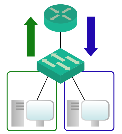
All in all, with RoaS we have a single physical link that contains multiple logical links (one per VLAN).
Inter-VLAN Routing with RoaS Lab
Preparing the Switch Domain
With Switch Domain, we mean the group of switches that share the same VLANs. Since everything but the client is blank for this lab, we need to configure the Layer 2 connectivity too. This is not strictly related to Inter-VLAN routing, but it is a good exercise for a real-life job. Furthermore, if you struggle with those commands, you can find all the help you need in the article about VLANs configuration.
Creating VLANs
For this lab, we are going to work with three VLANs: red, blue, and green. Their respective IDs are 10, 20, and 35 (as from the table at the beginning). We don’t need to do any fancy configuration, so we can just push all the VLANs on all the switches using the commands below.
vlan 10
 name Red
vlan 20
 name Blue
vlan 35
 name Green
This will create the VLANs, and associate them with a name. Now we just need trunks to allow the communication on the same VLAN between different switches.
Configuring Trunks
Trunks are a simple way to allow traffic from multiple VLANs to span over a single link. Considering that we are working with three VLANs, we definitely need trunks. SW-Left will have a trunk toward SW-Center:
interface FastEthernet0/24
 switchport trunk allowed vlan 10,20,35
 switchport mode trunk
 switchport nonegotiate
Also SW-Right will have a trunk toward SW-Center, but on a different interface.
interface FastEthernet0/23
 switchport trunk allowed vlan 10,20,35
 switchport mode trunk
 switchport nonegotiate
Then, SW-Center also needs trunks configuration. Specifically, it needs two ports (the one facing SW-Left and the one facing SW-Right) as below.
interface FastEthernet0/23
 switchport trunk allowed vlan 10,20,35
 switchport mode trunk
 switchport nonegotiate

interface FastEthernet0/24
 switchport trunk allowed vlan 10,20,35
 switchport mode trunk
 switchport nonegotiate
Access Ports
The last thing we need to do is the configuration of access ports. By default, all ports are in VLAN 1. To effectively put each device in the correct VLAN, just enter the following commands.
! These commands for SW-Left
int fa0/1
 switchport mode access
 switchport access vlan 35
int fa0/2
 switchport mode access
 switchport access vlan 35
int fa0/3
 switchport mode access
 switchport access vlan 10
int fa0/4
 switchport mode access
 switchport access vlan 10

! These commands for SW-Center
int fa0/5
 switchport mode access
 switchport access vlan 35
int fa0/6
 switchport mode access
 switchport access vlan 20

! These commands for SW-Right
int fa0/7
 switchport mode access
 switchport access vlan 10
int fa0/8
 switchport mode access
 switchport access vlan 10
int fa0/9
 switchport mode access
 switchport access vlan 20
int fa0/10
 switchport mode access
 switchport access vlan 20
And here we are! With that, we completed all the preliminary configuration. We can now focus on the real deal, which is Inter-VLAN Routing using RoaS.
Configuring Router on a Stick (RoaS)
Configuring Router on a Stick is simpler than you might think. We need to tell both the switch and the router how to talk with one another, so we will configure both of them.
The Switch side
Since configuring the switch is the simplest task, we will proceed with that first. In order to do Inter-VLAN Routing, the router must know about all the VLANs and access them. We already know which is the way to propagate multiple VLANs on a single link: a trunk. For this task, we just need to configure a trunk going from the switch to the router. The interface on SW-Center is GigabitEthernet 0/1, and we can configure it like any other trunk.
interface Gi 0/1
 switchport trunk allowed vlan 10,20,35
 switchport mode trunk
 switchport nonegotiate
Simple uh? Actually, there is nothing new in this part of the configuration. It is exactly a trunk like any other. However, what really matters is the router-side of the configuration.
Introducing the Router Side
At this point, our router can receive and send traffic on VLANs 10, 20, 35, and 1 (native). However, we need to instruct it on how to use those VLANs. Cisco routers have no concept of trunk, but they can handle the trunk protocol 802.1q.
To allow inter-VLAN routing, we need to configure the interface connecting the switch as blank. Then, we use logical interfaces to use that blank interface as a physical link. Cisco calls those interfaces subinterfaces, or subifs, because they rely on the blank interface which is a physical one. We need to create one subinterface for each VLAN we want to do routing for. In each, we can specify the encapsulation type (802.1q) and the IP address. Then, the router will treat these subifs as “real” links from a Network perspective.
First, we turn on the interface facing to the switch.
interface GigabitEthernet 0/1
 no shutdown
This is the physical interface. At this point, you should see the lights on the link turn green. However, we have just enabled L1 and L2 connectivity. We still need to configure Layer 3 routing
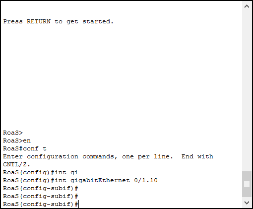
Configuring the Subinterfaces
To create a subinterface, issue the interface command, followed by the physical interface, a dot, and the number of logical interface we want to create. As an example, with interface Gi 0/1.10 command, we can effectively create the subinterface 10 of physical interface GigabitEthenet 0/1. The subinterface ID is just a label, and it does not need to match with the VLAN ID. However, it is a good practice to use the same number used for the VLAN ID. By issuing this command, we enter the subinterface prompt.
Now we just created a subinterface, but before we can assign an IP address to it, we need to specify the encapsulation type. By doing so, we not only tell the router which protocol to use, but we also tell which VLAN ID to use. The command for that is encapsulation, and it binds the subinterface with the VLAN ID. The syntax is “encapsulation”, followed by the protocol, followed by the VLAN ID.
After that, we can assign an IP address to the subinterface like any other physical interface. Here’s the complex syntax for that.
interface GigabitEthernet 0/1.10
 encapsulation dot1q 10
 ip address 10.0.10.1 255.255.255.0
Configuring other Subinterfaces
We just need to create two more subinterfaces, one for VLAN 20 and the other for VLAN 35. This is possible by using the same commands we already learned.
interface GigabitEthernet 0/1.20
 encapsulation dot1q 20
 ip address 10.0.20.1 255.255.255.0

interface GigabitEthernet 0/1.35
 encapsulation dot1q 35
 ip address 10.0.35.1 255.255.255.0
What if we want to do routing for the native VLAN? By default, the encapsulation command works with the 802.1q frame, and the VLAN tag contained in it. However, frames from the native VLAN comes untagged into the router. As a result, there is no VLAN tag to bind, but we need to explicitly specify that to the router. To do that, we can add the keyword “native” to the encapsulation command. This way, all untagged frames will be considered part of that interface. Here’s an example (enter it in the lab for scoring purposes).
interface GigabitEthernet 0/1.1
 encapsulation dot1q 1 native
And that’s all! We finally configured our Inter-VLAN routing with RoaS. You should now see your score going up to 100%, if not double-check the commands you inserted against the ones above. Once you are OK with your scoring, we can proceed with a little bit of analysis on what we did and how the router works.
Verify Router on a Stick
Check if Inter-VLAN Routing is working
With Inter-VLAN routing in general, there’s only one thing to verify. Since the major goal for this is the communication between VLANs, all we need to test is that. However, we don’t want just that. Instead of stopping there, we also want to be sure that traffic is effectively flowing through our RoaS device. For this purpose, the perfect tool is traceroute.
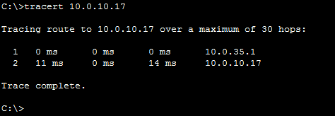
tracert command from PC0 trying the IP of PC7.As you can see from the picture, the traffic does not reach directly the target device. Instead, it passes through 10.0.35.1, which is our RoaS router. With all traffic passing from there, we can apply specific policies to restrict some types of traffic to pass from a VLAN to another. In other words, we just achieved a central point of management.
Checking Routes
Another interesting thing we can check is the routes installed int our RoaS router. To do that, we can simply hop in and issue our beloved show ip route. Below the expected output.
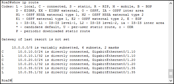
When you assign an IP address to an interface, the router automagically creates a Connected and Local route. Then, every time it receives a packet for those destinations, it knows what is the associated interface. By having those connected routes, we effectively enable Inter-VLAN routing. Ensure you have one connected route for each VLAN, otherwise, Inter-VLAN routing won’t work properly.
Further Troubleshooting
Sometimes, it just doesn’t work, and you need to know what to do. As we learned, the Router on a Stick is a very simple configuration. However, it entirely relies on the underlying VLAN infrastructure, so you need to check that too. As part of Inter-VLAN Routing troubleshooting, check that VLANs exist on all switches and that they are propagated correctly over trunks. If you check that, as well as the RoaS configuration, you’ll fix issues in minutes!
Conclusion
With this lab, we learned how to implement the communication between VLANs, as well as the theory behind it. Furthermore, we analyzed some items that may come very handy for troubleshooting. Here’s a quick recap of the commands used.
interface X/X.Yto create a subinterfaceencapsulation dot1q, followed by VLAN ID, to bind the subinterface with a VLANencapsulation dot1q 1 native, to bind the subinterface to the native VLAN (in this case VLAN 1)ip addressto assign an IP address to a subinterface (like any other interface)traceroute(ortracerton Microsoft) to verify traffic is passing through the RoaS
Our knowledge is increasing as we proceed through the CCNA Course. At this point, we are able to create a simple office that involves some segregation (such as servers and end-devices). But our journey doesn’t end here, there are a lot of technologies we might want to learn about in order to create bigger and better networks. For these, just continue following our Free CCNA Course!


2 Responses
wow good work that’s the what i do in lab for students
if you need more info check my account
Thank you! I sure will 🙂
Comments are closed.