
Any growing business is likely to have multiple sites. Whether you have a few branches, or plan connecting home workers, you may end up using the Internet. The Internet is fast, cheap, and world-wide available, unlike many private WAN technologies. However, it has a major flaw: it works with public addresses only. If you have a server with a private IP address, you can’t just expose it to the Internet. If the server should be public, you might want to use NAT. What if the server should be internal? In many cases, you want all the remote sites to access the servers in your main site, but don’t want anyone else to access them. With a GRE Tunnel (Generic Routing Encapsulation), you can emulate a private network while having only Internet links. In this article, we will see how to do it.
This article teaches you how to configure a GRE tunnel between two routers. Since we are going to use some new configuration commands, we have created a Packet Tracer lab. You can download it for free with the link below.

Once you do, unzip it and run it with Packet Tracer. You will be able to try the commands in the lab, and you will learn GRE Tunnels in minutes. Don’t worry, before starting with the lab we are going to cover all the needed theory.
GRE Tunnel Lab Intro
Lab Topology
For this lab, we have four visible routers and some others within the “WAN” cloud. Specifically, we have two routers we have control of: R1 and R2; and two routers from the provider: CE01 and CE02.
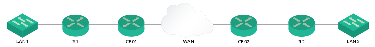
The topology is quite simple: all routers are lined up in a row, and R1 can already communicate with R2 using the public addresses. However, the two LANs on the routers have private addresses, and can’t communicate with each other.
The Requirements
Our requirement is clear: we need to establish a tunnel to allow communication between the two LANs. This tunnel shouldn’t be encrypted and should use the standard GRE encapsulation. We will also need to take care of the routes that instruct the routers on how to use the tunnel. While doing so, we can only use static routes and no dynamic protocol.
The tunnel must use the 192.168.1.0/30 addressing plan, with R1 having the lowest address.
A quick overview of GRE Tunnels
GRE stands for Generic Routing Encapsulation, and it is an extremely simple form of tunneling. Using the GRE protocol, you can create virtual links between routers, that allows them to be directly connected, even if they physically aren’t.
To do that, we leverage encapsulation. Every time a router decides than an IP packet should go into a GRE tunnel, it takes the whole packet and put it inside another IP packet. The internal IP packet will be the original one, of course. The outer IP packet, instead, delivers the whole thing to the remote router. The remote router will remove the outer packet, and continue forwarding the inner packet as usual.
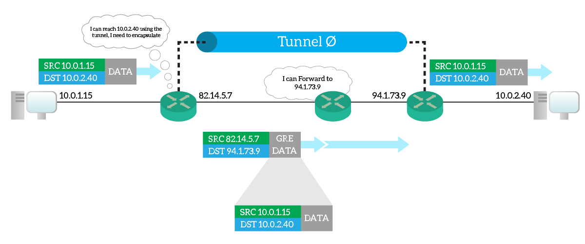
This way, the only two routers knowing routing information about the inner packet needs to be the two terminating the tunnel. Other routers will just route with the information from the outer packet. As a result, you are creating a virtual tunnel between the two tunnel-termination routers.
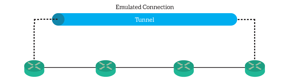
From a Layer 3 perspective, this link is like an ethernet link. You can assign it an IP address, run routing protocols on it, or configure it for static routes.
Configuring the GRE Tunnel
The Tunnel Interface
We know that the tunnel is a virtual link, obtained with encapsulation. The router can use this link like any other link, even if it’s virtual. A router has access to links through interfaces, so we need to create a virtual one to access the tunnel.
For this lab, we are going to create the Tunnel 0 interface, but any number would do. The tunnel numbers don’t need to match on the two routers. Enter in global configuration, and from there just enter interface tunnel 0. You will open the config-if prompt for the tunnel. Here, you can enter all the settings we are used to: IP addresses, routing protocol settings, and so on. However, just don’t do it for now.
By default, the protocol that a tunnel will use is GRE. Just to be sure, we can force it by typing tunnel mode gre ip inside the Tunnel interface. If this is the default, you won’t see it in the configuration. However, just type it to be sure, even in this lab.
Source and Destination
Before doing anything else, we should specify two tunnel-specific settings: source and destination. In fact, the router needs to know how to populate the outer IP packet when doing tunneling. With these two commands, we tell which IP address use as the source, and which as destination. However, you don’t specify directly the source IP address. You specify an interface instead: the router will automatically take the address of that interface. You can specify any type of interface you want, including loopbacks. The commands to do so are tunnel source and tunnel destination.
Hop on R1 and with show ip interface brief obtain the address of the public interface (GigabitEthernet 0/0). Do the same on R2 and you will know which is your destination address. Of course, R1 will have as destination R2, and vice versa. As a result, the configuration of R1 will look like this:
interface Tunnel0
 tunnel source GigabitEthernet0/0
 tunnel destination 91.29.73.100
And the one on R2 will be this:
interface Tunnel0
 tunnel source GigabitEthernet0/0
 tunnel destination 84.96.12.19
At this point, we have created a functioning Layer 2 link. We need to configure routing on it.
Configuring the routing
Configuring the routing is easy. We have one link, the tunnel, connecting two subnets. We will need to configure addresses on it, then add two static routes.
According to the requirements, the addressing plan for the tunnel is 192.168.1.0/30. So, we will need to enter ip address 192.168.1.1 255.255.255.252 on the Tunnel 0 of R1. Instead, we will need to use ip address 192.168.1.2 255.255.255.252 for R2. Now, ping from a router the address of the other. We expect this to work, but you won’t be able to ping the LAN behind the other router just yet.
To access the remote LAN, we need to add one static route per router. Specifically, we want to reach the remote LAN through the tunnel. So, hop into global configuration and type on R1 ip route 10.0.2.0 255.255.255.0 192.168.1.2. For R2, type ip route 10.0.1.0 255.255.255.0 192.168.1.1 instead.
Congratulations! You have now completed this lab about GRE Tunnels!
Verify and Troubleshoot GRE Tunnels
With GRE tunnels, there isn’t a lot going on. This is why packet tracer doesn’t implement specific show or debug commands. However, when troubleshooting a tunnel, you need to verify the source and destination. As usual, rely on show running-configuration and, most importantly, on show ip interface brief and show interface status. Ideally, the tunnel should always be up/up.
To verify that the tunnel is operating correctly, your best option is traceroute. Try that in the lab too, you will see that going from one LAN to the other now takes just one hop. This is because the tunnel is in use, and routers are using it as a virtual link. In fact, traceroute works with increasing TTLs in the IP packet. Routers in the path won’t be able to decrement the TTL of the inner packet, but only of the outer one. So, only the devices terminating the tunnel will be able to count as hops.
Remember, the GRE tunnel is plain data. If you send it over the Internet, someone might be able to open it and read it. However, you can add a level of encryption to hide your data on it. This is not part of the CCNA, but just know that it would be possible.
Conclusion
In this article, we learned how to create a virtual private link between two remote routers, using GRE. Now you have more flexibility when deciding what to do when implementing remote sites. To recap and collect all the useful commands in one place, check out the following list.
- GRE Tunnels creates a virtual link between routing by encapsulating IP packets into other IP packets
- Create a new tunnel or edit an existing one with
interface Tunnel <N>, the number doesn’t need to match on both routers - Force the tunnel to use GRE with
tunnel mode gre ip - Define the source and destination IP addresses of the outer packet using
tunnel sourceandtunnel destination - You can now use the tunnel as any other link, assign it an IP address and use it in static routes
With this, you are now gathering a lot of enterprise-level knowledge. You are now ready to learn about evaluating and selecting different options for WAN connectivity. But that’s for the next article!


4 Responses
such a gem!! Great work! Thank you.
Oh, I am happy you found it useful! Keep coming on ICTShore.com for the rest of the CCNA course, now we are almost at the end. After that, I will ask you what you would like to read next.. I have some cool things in mind 🙂 Thank you!
Thank you very much for your article. I love it. It’s very easy to understand!
Wish you all the best!
Hello Huy Than, I am very pleased by your words! Knowing you find my articles easy to understand is awesome, and keeps me going! So, whenever you like something, or want to give a suggestion, just let me know! Thank you!!
Comments are closed.